Manual 37128A GCP-20 Series - Genset Control
Page 22/190 © Woodward
Measuring Inputs
≡≡≡≡≡≡≡≡≡≡≡≡≡≡≡≡≡≡≡≡≡≡≡≡≡
NOTE
The following is valid for units with a software version older than V1.0700:
The three-phase system must have a clockwise rotary field (right-handed rotary field). If the unit is
used with a counter-clockwise rotary field (left-handed rotary field), the power factor measurement will
not be correct.
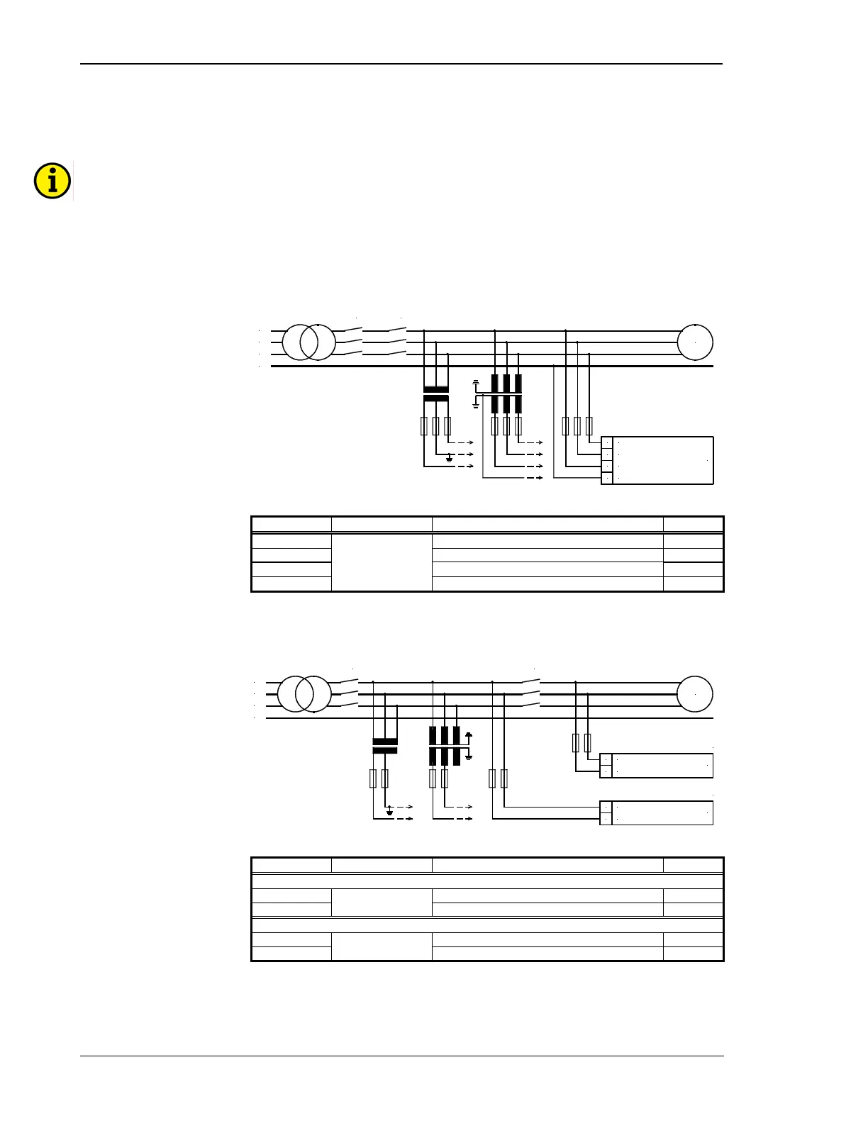
Voltage Measuring: Generator
L1
L2
L3
N
Generator voltage
MCB GCB
0
N
20 21 22
L3
L2
L1
G
Figure 6-2: Voltage measuring: generator
Terminal Measurement Description A
max
20 Generator voltage L1 2.5 mm²
21 Generator voltage L2 2.5 mm²
22 Generator voltage L3 2.5 mm²
0
400 V direct or
via../100 V meas-
urement transducer
Neutral point of the 3-phase system/transformer Solder lug
Table 6-2: Voltage measuring: generator - terminal assignment
Voltage Measuring: Busbar / Remanence
N
L1
L2
L3
Remanence voltage
Busbar voltage
23 24 23 24
L1
L2
L1
L2
MCB GCB
G
Induction
Synchronous
Figure 6-3: Voltage measuring: busbar / remanence
Terminal Measurement Description A
max
Induction version
23 Remanence voltage L1 2.5 mm²
24
direct
Remanence voltage L2 2.5 mm²
Synchronous version
23 Remanence voltage L1 2.5 mm²
24
400 V direct or
../100 V
Remanence voltage L2 2.5 mm²
Table 6-3: Voltage measuring: busbar / remanence - terminal assignment

 Loading...


