Manual 37128A GCP-20 Series - Genset Control
© Woodward Page 31/190
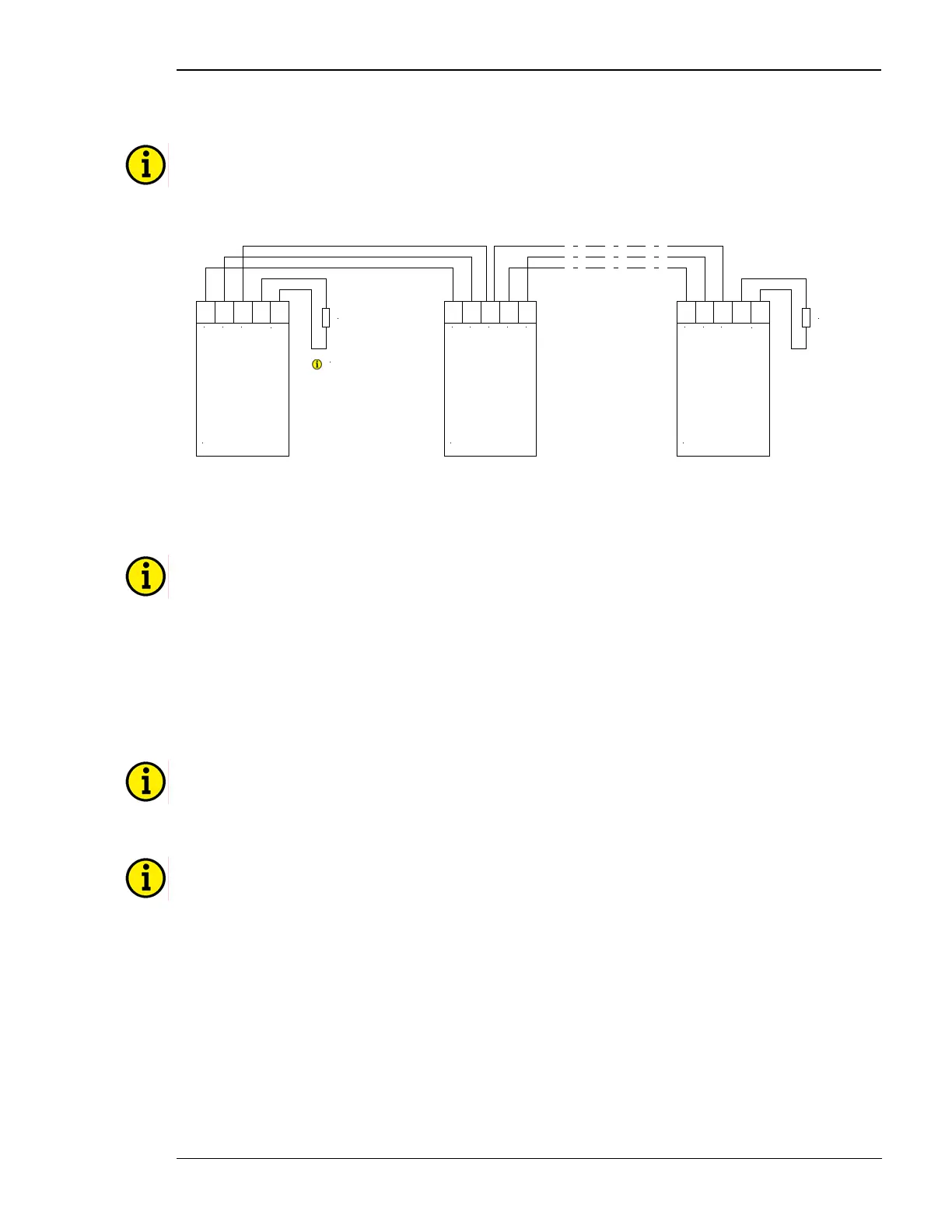
The CAN Bus Loop
NOTE
Please note that the CAN bus must be terminated with an impedance which corresponds to the wave
impedance of the cable (e.g. 120 Ohm). The CAN bus is terminated between CAN-H and CAN-L.
GND
CAN-L
CAN-H
GND
GND
CAN-L
CAN-H
CAN-L
CAN-H
CAN-L
CAN-H
CAN bus
Termination
Termination
resistor
Note:
The termination has to be
performed with a resisitance,
which corresponds to the
impedance of the used cable
(e.g 120 Ohms)
CAN bus CAN bus
Termination
Termination
resistor
Figure 6-21: Interfaces - Loop the CAN bus
DPC - Direct Configuration Interface
NOTE
To configure via the configuration interface (direct configuration) you need the configuration cable (or-
dering code "DPC"), the program LeoPC1 (delivered with the cable) and the corresponding configura-
tion files. Please consult the online help installed when the program is installed for a description of the
LeoPC1 program and its setup.
If the parameter "Direct config." is switched to ON the communication via the interface on termi-
nals X1/X5 is disabled.
If the control unit detects that the engine is running (ignition speed exceeded), the direct configuration
port is disabled.
NOTE
The DPC cable (P/N 5417-557) is intended for configuration and service operation only. Do not operate
the GCP-20 with the DPC plugged into the unit during regular operation.
NOTE
The connection cables delivered with the DPC must be used to connect between the control unit and
the computer to ensure a proper function of the GCP-20. Utilization of an extension or different cable
types for the connection between GCP-20 and DPC can result in a malfunction of the GCP-20. This may
possibly result in damage to components of the system. If an extension of the data connection line is
required, only the serial cable between DPC and notebook/PC may be extended.
Unplug the DPC after configuration to ensure a safe operation!

 Loading...


