Manual 37128A GCP-20 Series - Genset Control
Page 28/190 © Woodward
Auxiliary and Control Outputs
≡≡≡≡≡≡≡≡≡≡≡≡≡≡≡≡≡≡≡≡≡≡≡≡≡
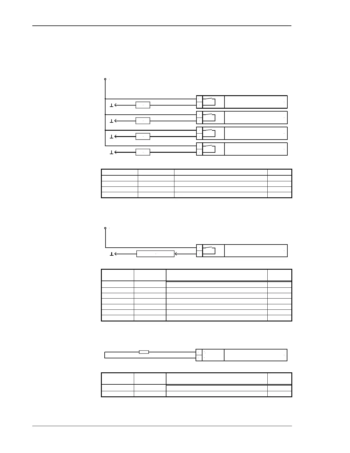
Power Circuit Breaker Outputs
max. 250 V AC
Command: close GCB
Command: close MCB
Command: open MCB
Command: open GCB
GCB
MCB
MCB
GCB
4142
14
1740 39 16 15
Figure 6-14: Power circuit breaker outputs
Root Switched Description A
max
14 15 Close generator power circuit breaker 2.5 mm²
16 17 Close mains power circuit breaker 2.5 mm²
39 40 Open mains power circuit breaker 2.5 mm²
41 42 Open generator power circuit breaker 2.5 mm²
Table 6-13: Power circuit breaker outputs - terminal assignment
Relay Outputs (general)
AB
Relay output
external device
max. 250 V AC
Figure 6-15: General relay outputs
Root Switched Description A
max
A B
18 19 Ready for operation 2.5 mm²
43 44 Fuel solenoid 2.5 mm²
45 46 Starter 2.5 mm²
33 34 Relay 1 (RM) 2.5 mm²
35 36 Relay 2 (RM) 2.5 mm²
37 38 Relay 3 (RM; pre-assigned: preheat / ignition ON) 2.5 mm²
47 48 Relay 4 (RM; centralized alarm horn) 2.5 mm²
Table 6-14: General relay outputs - terminal assignment
Analog Outputs (Option A2)
Analog output
0 V
A
B A
I
Figure 6-16: Analog outputs
0 V Description A
max
A B
120 121 Analog output 0/4 to 20 mA 2.5 mm²
122 123 Analog output 0/4 to 20 mA 2.5 mm²
Table 6-15: Analog outputs - terminal assignment

 Loading...


