Manual 37128A GCP-20 Series - Genset Control
Page 24/190 © Woodward
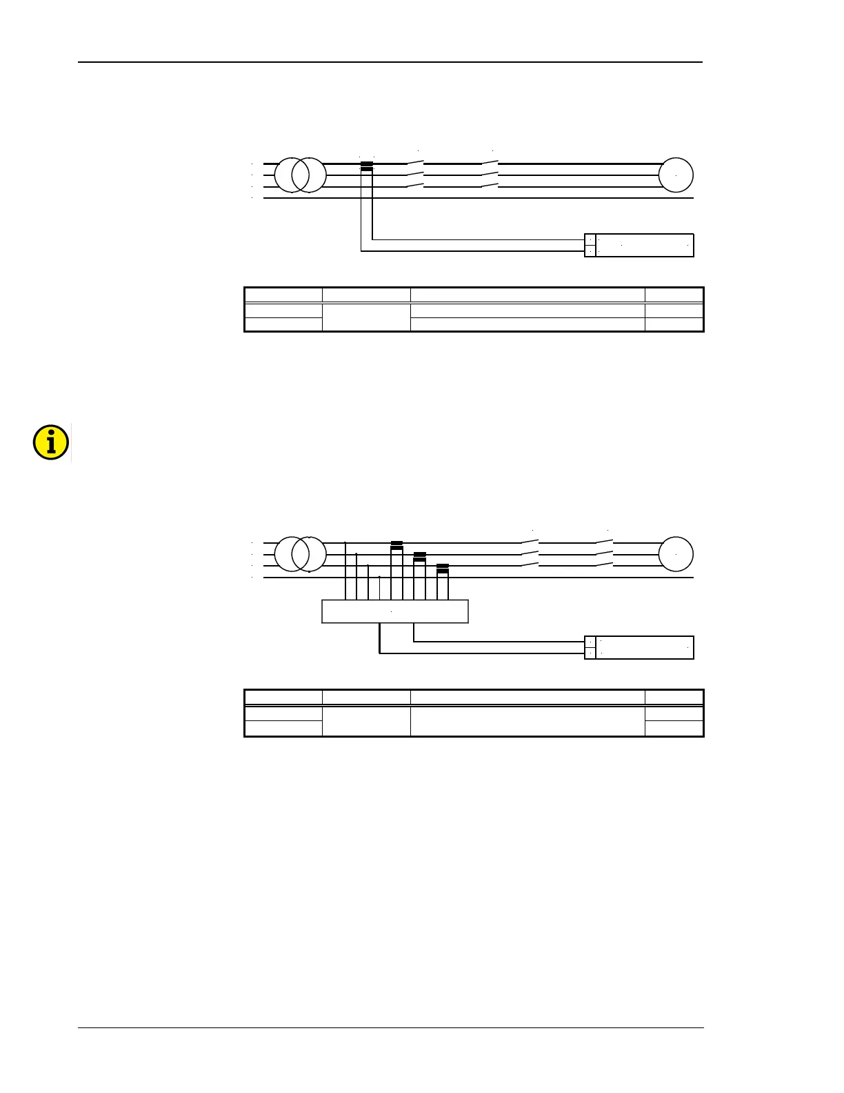
Current Measuring: Mains [GCP-21, GCP-22]
Standard Mains Measuring
L2
L3
L1
N
GCB
S1
s1
S2
s2
MCB
G
Mains current
../1A or ../5 A
s1 (k)
27 28
s2 (l)
L1
Figure 6-6: Current measuring: mains standard
Terminal Measurement Description A
max
27 Mains current L1, transformer terminal s2 (l) 2.5 mm²
28
Transformer
../1 A or ../5 A
Mains current L1, transformer terminal s1 (k) 2.5 mm²
Table 6-6: Current measuring: mains standard - terminal assignment
Mains Measuring with Option In20 (Power measurement via measurement transducer)
NOTE
If several units are connected to form an interconnection, the 20 mA measuring signal must not be
looped through all units. At each control, a 0/4
to 20 mA buffer amplifier must be connected to the
mains power input (terminals 27/28). When selecting the external measuring transformer, please note
that this has to transmit negative ranges on transmission of supply and reference power.
Measuring transducer
MCB GCB
Mains active power
0/4..20 mA
27 28
G
L2
L3
L1
N
+
-
Figure 6-7: Current measuring: mains Option In20
Terminal Measurement Description A
max
27 2.5 mm²
28
Analog signal
0 /4 to 20 mA
Mains active load via a 0/4 to 20 mA-signal of an
external measuring transducer (e.g. UMT 1)
2.5 mm²
Table 6-7: Current measuring: mains Option In20 - terminal assignment

 Loading...


