Manual 37128A GCP-20 Series - Genset Control
© Woodward Page 19/190
Analog output
0/4 to 20 mA
Analog output
manager
I
A
I
A
GND
GND
123122121120
LSX
A
U
GND
3
3
G
5
0 V DC
2005-07-21 / GCP-20 Anschlußplan Woodward gcp20ww-2905-ap.skf
1
9
6
7
8
A
B
C
D
E
50 51 52 53 54 23 24 41 14 15 4 25 2642 29 30 31 32 20 21 22 11 12 13 8 9 10 X1 X2 X3 X4 X5
0 1 2 3 5 6 7 33 34 35 36 60 61 62 63 64 65 66 67 68 69 70 71 18 19 43 44 45 46 90 91 92 93 94 95 96 97 98 99 100 101 102 103 104
L1
L2
s2 (l)
s1 (k)
s2 (l)
s1 (k)
s2 (l)
s1 (k)
12/24 V DC
N
131211
+/-5 V DC
A
U
GND
98
+/-3 V DC
10
higher
lower
Relay manager
(freely program-
mable relays)
Pickup
quasi-continuous controller with analog outputs
Drive
Printed 10/2001; subject to technical mocifications.
Mains voltage L1
Mains voltage L3
Mains voltage L2
GCB
Reply: GCB is open
higher
lower
Automatic 1
Ready for operation
Automatic 2
Multi-function terminal
Common (terminal 3/4/5/6/53/54)
Common
Input 1
(fault class 3: emergency STOP)
Input 5
Input 6
Input 7 or
Close GCB w/o engine monitoring
Input 9
Input 10
Input 11
Input 12
Input 13
Input 14
Start relay / Gas valve
Starter
Relay 1
Relay 2
Command: open GCB
Generator current L1
Generator current L2
Generator current L3
Generator voltage L1
Generator voltage L2
Generator voltage L3
Command: close GCB
The PC configuration plug
is located on the side of the unit.
This is where the DPC cable
must be plugged in.
Mains parallel
Isolated operation
GCP-21 Genset Control Package
Meaning Terminal 54 Terminal 53
Isolated
operation
YES
e.g. 24 V DC
NO
e.g. 0 V DC
Mains parallel
operation
NO
e.g. 0 V DC
YES
e.g. 24 V DC
CAN bus interface
Guidance level
GND
switching/inductive
GND
CAN-H
CAN-L
Termination
Relay 3
3837
Relay 4
484772 73 74
4
Input 3 or
Lock operation mode
3
Input 2 or
Crank terminate
2
27 28
s2 (l)
s1 (k)
Mains current L1
SPEED / POWER
(three-position controller)
LSB/LSR/LSX altern.:
Analog controller output
VOLTAGE / POW. FAC.
(three-position controller)
LSB/LSX alternative:
Analog controller output
up to 8 additional gensets
(each via one GCP-20)
Analog input 1 [T1]
VDO, 0 to 180 Ohm
(0 to 5/10 bar or 0 to 27/145 psi)
Analog input 2 [T2]
VDO, 0 to 380 Ohm (40 to 120 °C)
Analog input 3 [T3]
Externe Sollwertvorgabe
0/4 to 20 mA
Analog input 4 [T4]
0/4 to 20 mA
Control room
SPS
PC
GATEWAY
GW 4
Standard =
Centralized alarm
Standard =
Ignition / preglow
Busbar voltage
all
all
allallall
LSR/LSX
Input 8
Input 4
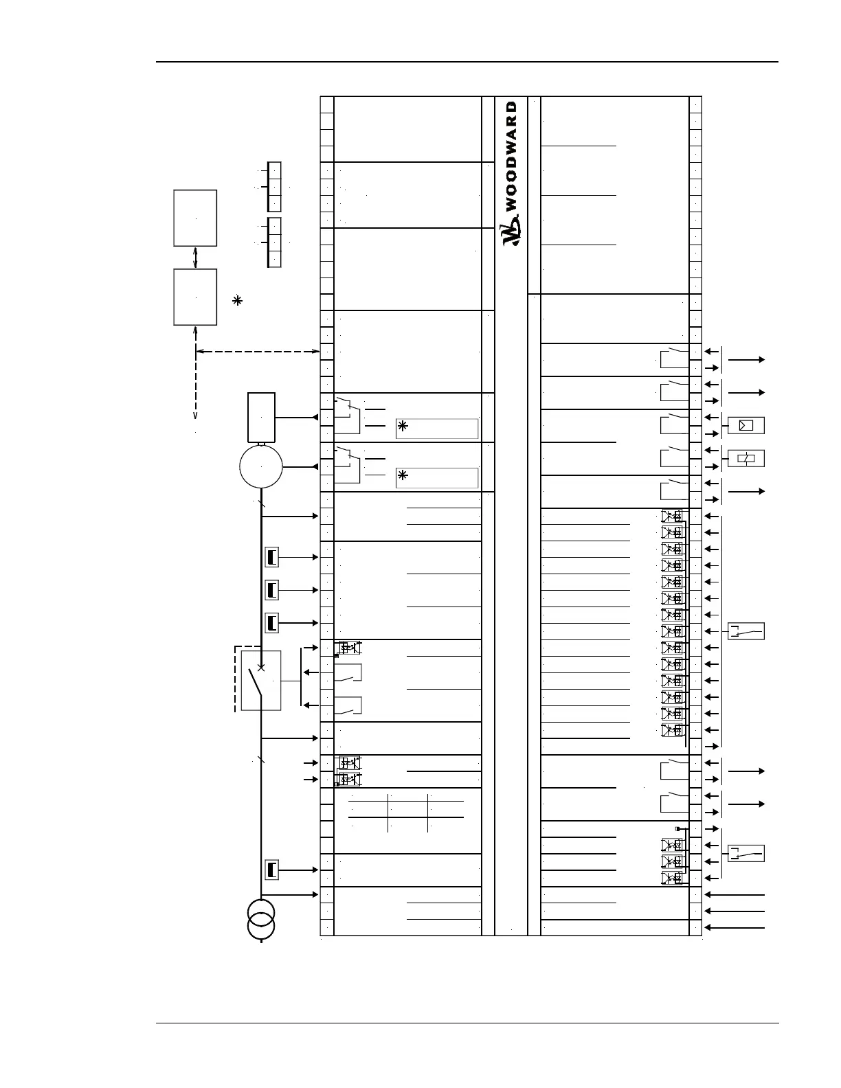
Figure 5-2: Wiring diagram - GCP-21

 Loading...


