Manual 37128A GCP-20 Series - Genset Control
© Woodward Page 13/190
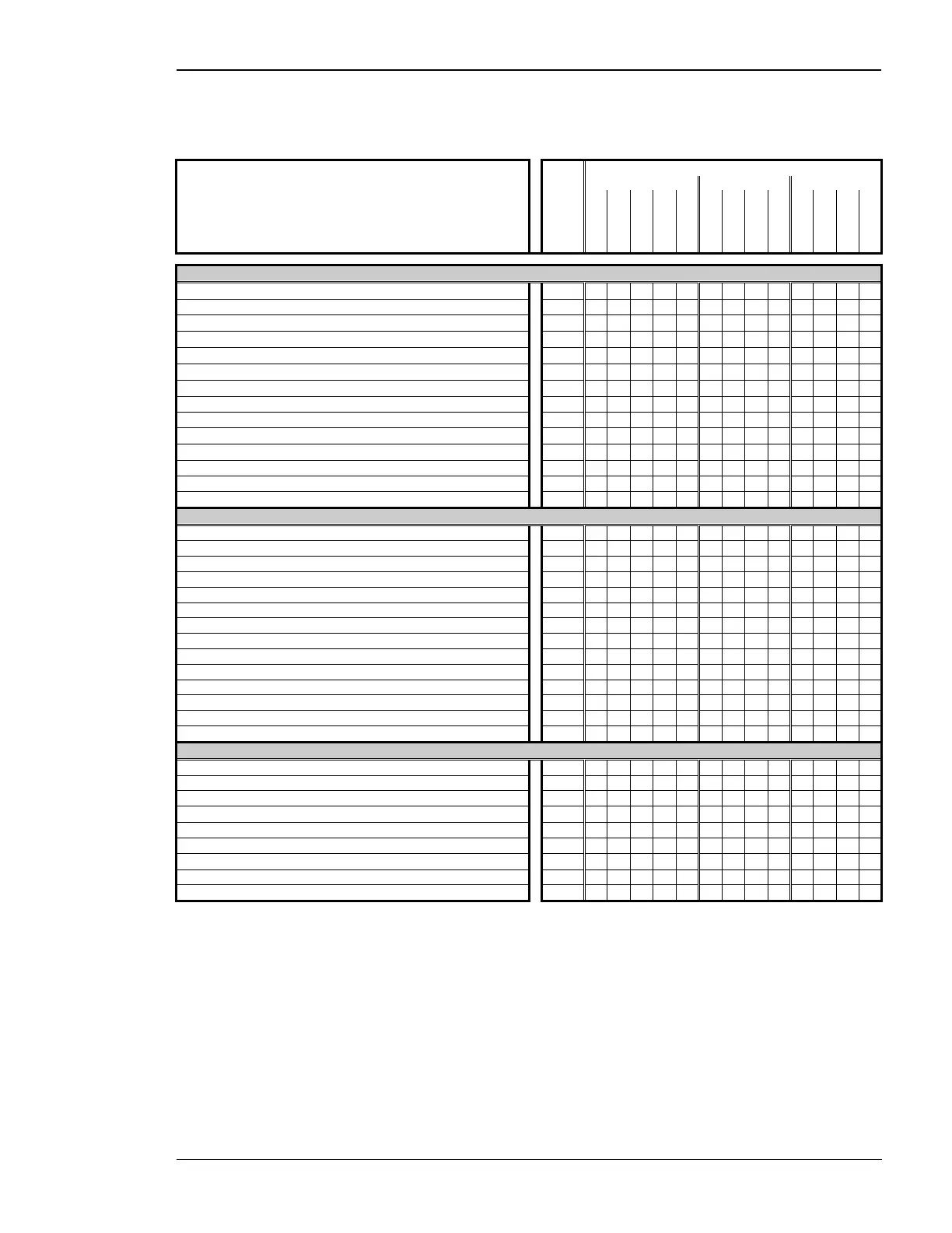
Functional Overview
≡≡≡≡≡≡≡≡≡≡≡≡≡≡≡≡≡≡≡≡≡≡≡≡≡
Function Package
GCP-20 GCP-21 GCP-22
Option
T2
LS
B
X
LSX
LS
LSB
LSR
LSX
LS
LSB
LSR
LSX
Common functions
1× ready for operation relay
Std.
9 9 9 9 9 9 9 9 9 9 9 9 9
4/6× control relay (form A, make contact)
Std.
9 9 9 9 9 9 9 9 9 9 9 9 9
4× freely configurable relay outputs (form A, make contact)
Std.
9 9 9 9 9 9 9 9 9 9 9 9 9
2× three-position controller for n/f/V/P, power factor
Std.
9 9
-- -- 1
9
-- 1 --
9
-- 1 --
2× analog controller outputs for n/f/V/P/Q
-- --
9 9
1 --
9
1
9
--
9
1
9
6× discrete control inputs
Std.
9 9 9 9 9 9 9 9 9 9 9 9 9
14× discrete alarm inputs
Std.
9 9 9 9 9 9 9 9 9 9 9 9 9
CAN bus interface 'Guidance level' Std.
--
9
--
9 9 9 9 9 9 9 9 9 9
4× analog inputs
2 -- --
9 9
-- --
9 9
-- --
9 9
1× Pickup input
Std.
9 9 9 9 9 9 9 9 9 9 9 9 9
2× analog outputs + external op. mode selection by term. 127/128
A2
-- -- -- -- -- -- -- --
9
-- -- --
9
Password system Std.
9 9 9 9 9 9 9 9 9 9 9 9 9
Configuration via DPC possible (direct configuration) Std.
9 9 9 9 9 9 9 9 9 9 9 9 9
Running hours, maintenance, start, and kWh counter Std.
9 9 9 9 9 9 9 9 9 9 9 9 9
Control/synchronization
Synchronization of 1 breaker with V and f correction Std.
-- -- -- -- --
9 9 9 9
-- -- -- --
Synchronization of 2 breakers with V and f correction Std.
9 9 9 9 9
-- -- -- --
9 9 9 9
Closing to a dead/voltage free busbar (dead bus start) Std.
9 9 9 9 9 9 9 9 9 9 9 9 9
Voltage control Std.
9 9 9 9 9 9 9 9 9 9 9 9 9
power factor control Std.
-- -- -- -- --
9 9 9 9 9 9 9 9
Speed/frequency control Std.
9 9 9 9 9 9 9 9 9 9 9 9 9
Generator real power control & import/export real power control Std.
-- -- -- -- --
9 9 9 9 9 9 9 9
Real & var sharing Std.
9
9 9 9 9 9 9 9 9 9
Analog set point value for real power
T4 -- -- -- -- -- -- -- --
9
-- -- --
9
Breaker logic "open transition" & "closed transition" Std.
9 9 9 9 9
-- -- -- --
9 9 9 9
Breaker logic "soft loading" Std.
9 9 9 9 9
-- -- -- --
9 9 9 9
Breaker logic "parallel operation" Std.
9 9 9 9 9 9 9 9
Breaker logic "external" Std.
9 9 9 9 9 9 9 9 9 9 9 9 9
Remote control via interface Std.
9
9 9 9 9 9 9 9 9 9 9
Over-/undervoltage protection, generator V
gen
>/< Std.
9 9 9 9 9 9 9 9 9 9 9 9 9
Over-/undervoltage protection, mains V
mains
>/< Std.
-- -- -- -- --
9 9 9 9 9 9 9 9
Over-/underfrequency protection f>/< Std.
9 9 9 9 9 9 9 9 9 9 9 9 9
dϕ/dt vector/phase jump protection dϕ/dt
Std.
-- -- -- -- --
9 9 9 9 9 9 9 9
Reverse/reduce power protection +/-P
gen
< Std.
9 9 9 9 9 9 9 9 9 9 9 9 9
Overload protection P
gen
> Std.
9 9 9 9 9 9 9 9 9 9 9 9 9
Load imbalance protection
ΔP
gen
>
Std.
9 9 9 9 9 9 9 9 9 9 9 9 9
Time-overcurrent protection I
toc
>/>> Std.
9 9 9 9 9 9 9 9 9 9 9 9 9
Battery voltage protection V
bat
< Std.
9 9 9 9 9 9 9 9 9 9 9 9 9
1) n/F analog, V raise/lower
2) only two analog inputs
Table 2-1: Functional overview
The GCP-20 series consists of three models which are intended for different applications and requirements. This
manual covers all available versions of the GCP-20. Please take information about the differences between the
units from this section.

 Loading...


