Manual 37128A GCP-20 Series - Genset Control
© Woodward Page 21/190
Chapter 6.
Connections
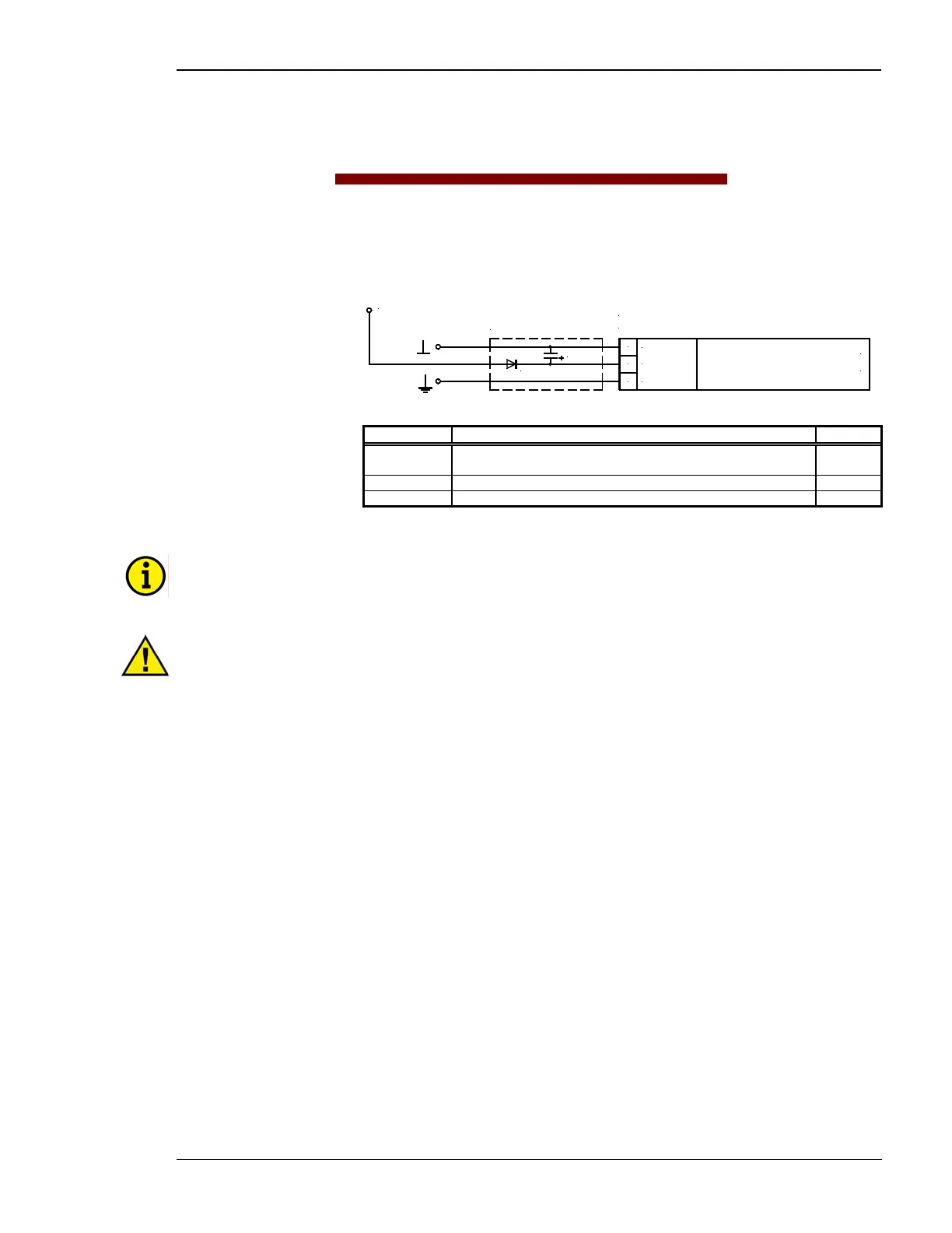
Power Supply
≡≡≡≡≡≡≡≡≡≡≡≡≡≡≡≡≡≡≡≡≡≡≡≡≡
0 1 2
N
0 V
D1
C1
D1 = P600M
for 12 V DC systems
Power supply
8 to 36 V DC (in normal operation)
(min. 12 V DC to start)
C1 = 47,000 uF / 40 V
8 to 36 Vdc
8 to 36 Vdc
Figure 6-1: Power supply
Terminal Description A
max
0
Neutral point of the three-phase system or neutral terminal of the volt-
age transformer (Measuring reference point)
Solder lug
1 0 Vdc reference potential 2.5 mm²
2 8 to 36.0 Vdc, 8 W 2.5 mm²
Table 6-1: Power supply - terminal assignment
NOTE
When using the device in 12 V systems, wire the power supply as indicated above.
CAUTION
Ensure that the engine will be shut down by an external device in case the power supply of the GCP-20
control unit fails. Failure to do so may result in damages to the equipment.

 Loading...


