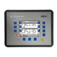
Manual 37128A GCP-20 Series - Genset Control
Page 32/190 © Woodward
Chapter 7.
Functional Description
Considerations for …
≡≡≡≡≡≡≡≡≡≡≡≡≡≡≡≡≡≡≡≡≡≡≡≡≡
… Different Options
In accordance with its configuration, the unit may differ from the maximum expansion via the following charac-
teristics:
• The inputs and outputs may be installed or not. Please check the wiring diagram and the notes referring to
the corresponding options. Refer to the type plate to see whether or not the corresponding option is con-
tained in the unit. If the type plate was removed you can scroll through all configuration masks and combine
individual options with the aid of this manual.
• There are various configuration masks for the various types of interfaces.
… Equipment with One Power Circuit Breaker
If a unit with a 2-circuit breaker logic circuit [GCP-22] or with a 1-circuit breaker logic circuit [GCP-21] is used
for an application with one power circuit breaker, the following applies:
• If the equipment is to be operated in isolated operation, the following signals must be deposited (as a rule,
the following applies: Term. 53 always negated to term. 54):
- Set mains decoupling to "GCB",
- "Response: MCB is open" / "isolated operation" (term. 54): HIGH signal (log. "1") and
- "MCB enable" (terminal 53): LOW signal (logic "0").
- Condition: The "emergency power" screen must be configured "OFF".
• If the equipment is to be operated in parallel operation, the following signals must be deposited (as a rule,
the following applies: Term. 53 always negated to term. 54):
- "Reply: MCB is open" / "isolated operation" (term. 54): LOW signal (log. "0") and
- "MCB enable" (terminal 53): HIGH signal (logical "1").
- Set mains decoupling to "GCB",
- Condition: The "emergency power" screen must be configured "OFF".
… Equipment with Induction Generators
If systems with induction generators are used, the following must be noted:
• Systems with induction generators are 1-LS-equipments [GCP-21].
• Connect the remanent voltage to the terminals 23/24. Terminal 23/24 has a zoom function as long as the
unit is not operated in parallel with the mains, as the unexcited synchronous generator is not yet able to
generate voltage. If the unit is operated in parallel with the mains, this input is no longer taken into consid-
eration. Control is carried out on the basis of voltage measurement at terminals 20/21/22 and 50/51/52.
• Connect the terminal 53 " MCB enable" to a continuous HIGH signal (e. g. connect with the terminal 1
"power supply"). This informs the unit that it is in mains parallel operation. Power control is carried out.
• Connect the terminal 54 " MCB reply" to a continuous LOW signal
 Loading...
