Manual 37128A GCP-20 Series - Genset Control
© Woodward Page 27/190
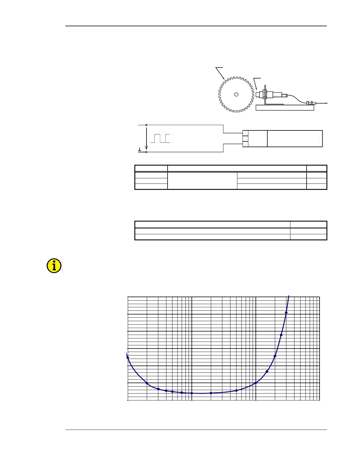
MPU Input (Pickup)
≡≡≡≡≡≡≡≡≡≡≡≡≡≡≡≡≡≡≡≡≡≡≡≡≡
Sensor
to
Pickup
input
Rotating shaft
Figure 6-11: MPU - principle overview
24 V
Pickup
swiching/inductive
< 1.0 V
9091
GND
92
sw./ind.
Figure 6-12: MPU input
Terminal Description A
max
90 inductive/switching 2.5 mm²
91 2.5 mm²
92
MPU input
GND 2.5 mm²
Table 6-11: MPU - terminal assignment
Specification of the input circuit for inductive speed sensors
Ambient temperature: 25 °C
Signal forming sinusoidal
Minimum input voltage of 200 to 10,000 Hz < 0.5 V
eff
Minimum input voltage of 300 to 5,000 Hz < 0.3 V
eff
Table 6-12: MPU - minimum input voltage
NOTE
When the ambient temperature rises, the minimum input voltage is increased by approx. 0.3 V/°C.
Input Voltage in Dependence of the Frequency [Ueff]
0
0,5
1
1,5
2
2,5
3
100 1000 10000 100000
Frequency [Hz]
Effective Input Voltage [V]
Figure 6-13: Minimum required input voltage depending on frequency at 25°C

 Loading...


