Manual 37128A GCP-20 Series - Genset Control
Page 56/190 © Woodward
Terminal
resistance
Note:
The termination must be
effected with a resistor
which corresponds to the
wave impedance of the
used cable (e. g. 100 )
CAN bus
X4
CAN-H
CAN-L
GND
X1 X2 X3
Termination
X5
Ω
CAN bus
CAN-H
X1
Terminal
resistance
CAN-L
CAN-H
CAN-L
X5
GND
X3X2 X4
CAN-L
X2
CAN-H
X1
CAN bus
Termination
X4
GND
X3 X5
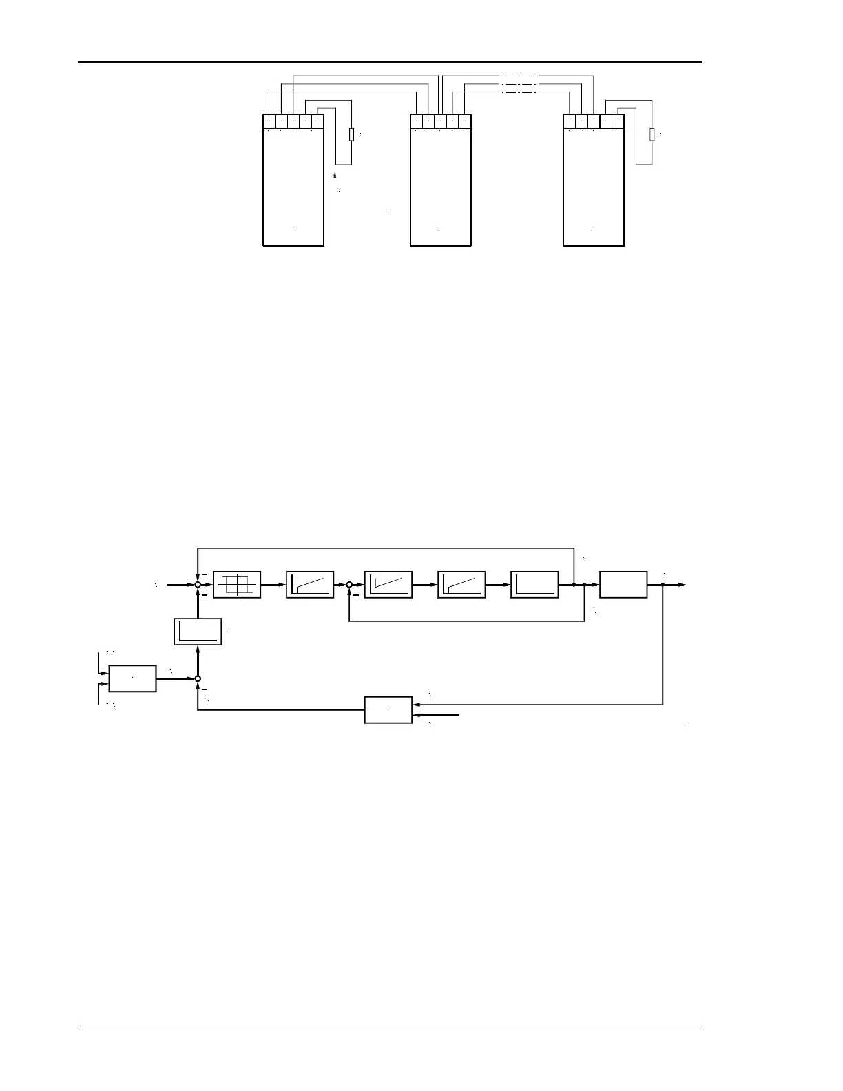
Figure 7-5: CAN bus wiring
Schematic Representation of Load Sharing via CAN Bus
Whether a genset is carrying out a load sharing and frequency control while in isolated operation in parallel with
other gensets, and to which extent, is determined by the parameter "load sharing reference input value " which is
expressed as a percentage value. In this case, 10 % means increased active power control, and 99 % increased
frequency control. This parameter must be input individually for each unit.
In the case of the following control system, it must be noted that each unit calculates the mean utilization factor
of all units from the data transmitted via the CAN bus, and then compares this with its own utilization factor. The
utilization factor is compared with the reference variable, and results in the new reference variable. Frequency
and active power control are simultaneously carried out in these units (corresponding to the reference variable).
Frequency control is carried out via the measured voltage/frequency of the voltage system. The pickup is only
used for monitoring functions.
P
f
actual [kW]
nominal [kW]
actual [Hz]
Utilization factor of this engine [%]
P
P
P
Σ
Calculation
actual (via CAN)
diff [%]
f
P
Σ
set
nominal (via CAN)
Leading value 10..99 [%]
10 % = only P control
99 % = only f control
P
P
Calculation
2001-08-06 Leistungsverteilung Blockschaltbild.skf
actual [kW]
n
actual [min-1]
Figure 7-6: CAN bus scheme

 Loading...


