Manual 37128A GCP-20 Series - Genset Control
Page 54/190 © Woodward
Power Direction
≡≡≡≡≡≡≡≡≡≡≡≡≡≡≡≡≡≡≡≡≡≡≡≡≡
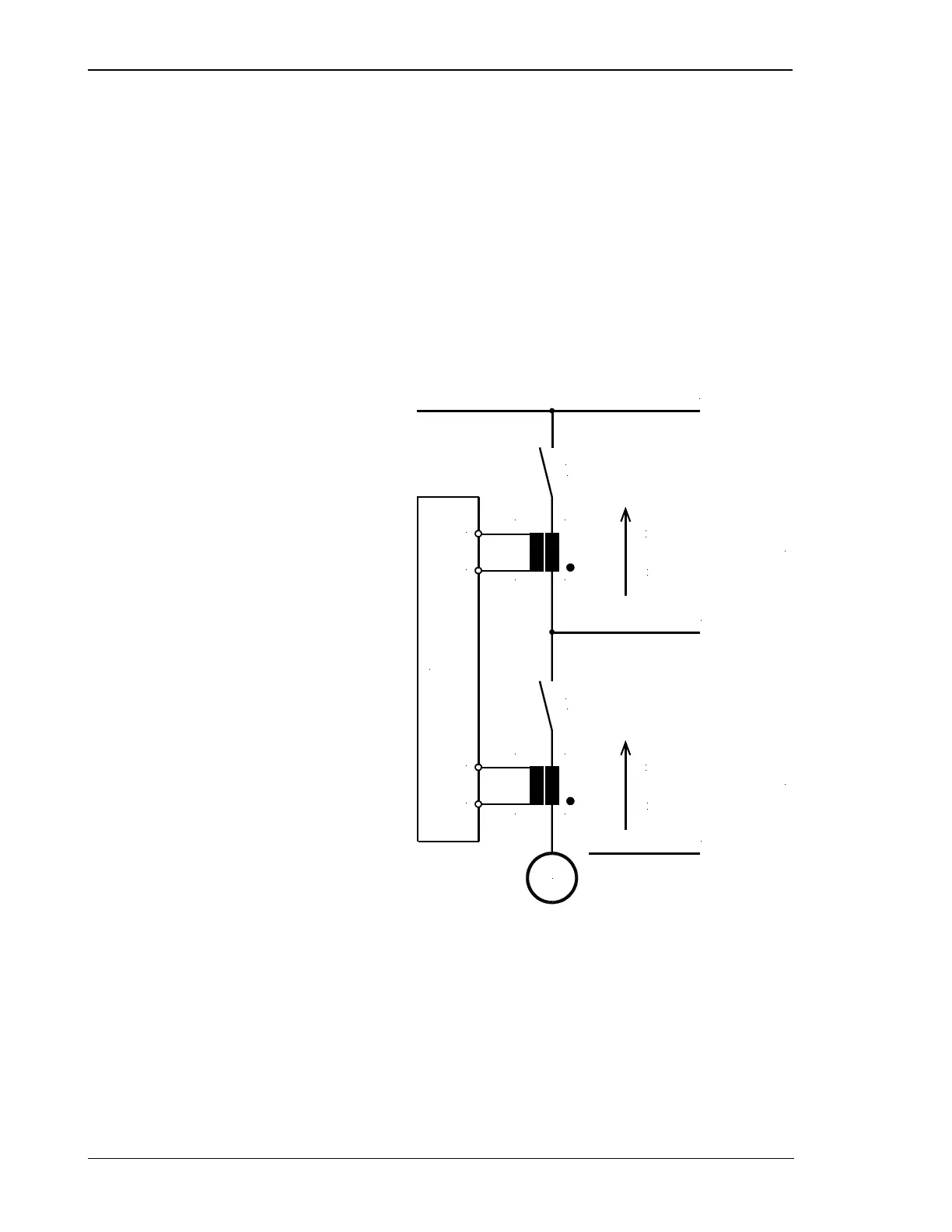
If the unit's current transformers are wired according to the pin diagram shown, the following values are dis-
played:
Positive generator active load
The generator supplies active load.
Inductive generator power factor
The generator is overexcited and supplies inductive reactive power.
Positive mains active load
Active load is supplied to the mains.
Inductive mains power factor
The mains picks up inductive reactive power.
S1 (K)
S2 (L)
S2 (L)
S1 (K)
Active power
Dispaly positive
Reactive power
Display inductive
Active power
Display positive
Reactive power
Display capazitive
GCB
generator circuit breaker
MCB
mains circuit breaker
GCP-20
26
25
s1 (k)
G
s2 (l)
28
27
s1 (k)
s2 (l)
pospos
GENERATOR
indind
QQ
PP
pospos
indind
QQ
PP
BUSBAR
MAINS
Figure 7-4: Power direction

 Loading...


