October 2012
7-12
ColorQube 8570/8870 Service Manual
Wire Routing Diagrams
Revised, 3rd Revision - Xerox Internal Use Only
Wiring Data
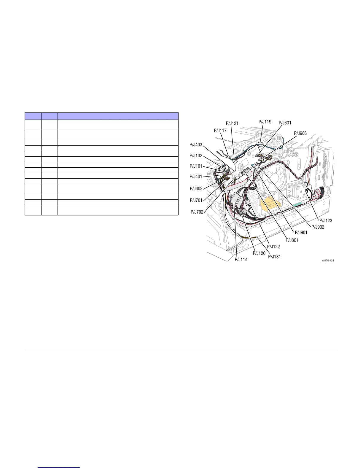
Right Side Wiring
Figure 1 Right Side Wire Routing
P/J301 Figure 2 Connects the Power Control Board (Electronics Module) to the Y-Axis
Motor.
P/J302 Figure 2 Connects the Power Control Board (Electronics Module) to the Left Side
Harness.
P/J401 Figure 1 Connects the I/O Board to the Preheater and Tray 2 Sensors.
P/J402 Figure 1 Connects the I/O Board to the Paper Size Switch.
P/J403 Figure 1 Connects the I/O Board to the Control Panel.
P/J601 Figure 1 Connects the I/O Board to the Exit Module.
P/J701 Figure 1 Connects the I/O Board to the Paper Size Sensor.
P/J702 Figure 1 Connects the I/O Board to the Ink Loader Board.
P/J801 Figure 1 Connects the I/O Board to the Power Control Board (Electronics Module).
P/J901 Figure 1 Connects the I/O Board to the Drum Maintenance Pivot Plate.
P/J901 Figure 2 Connects the Power Control Board (Electronics Module) to the Wave
Amplifier.
P/J902 Figure 1 Connects the I/O Board to the Drum Temperature Sensor.
P/J903 Figure 1 Connects the I/O Board to the Drum Fan.
P/JAC2 Figure 6 Connects the printer Power Supply (Electronics Module) to the Printhead
Heaters.
Table 1 Wire Routing Location
P/J Map Remarks
 Loading...