October 2012
8-14
ColorQube 8570/8870 Service Manual
Printer Electronics
Revised, 3rd Revision - Xerox Internal Use Only
Theory of Operation
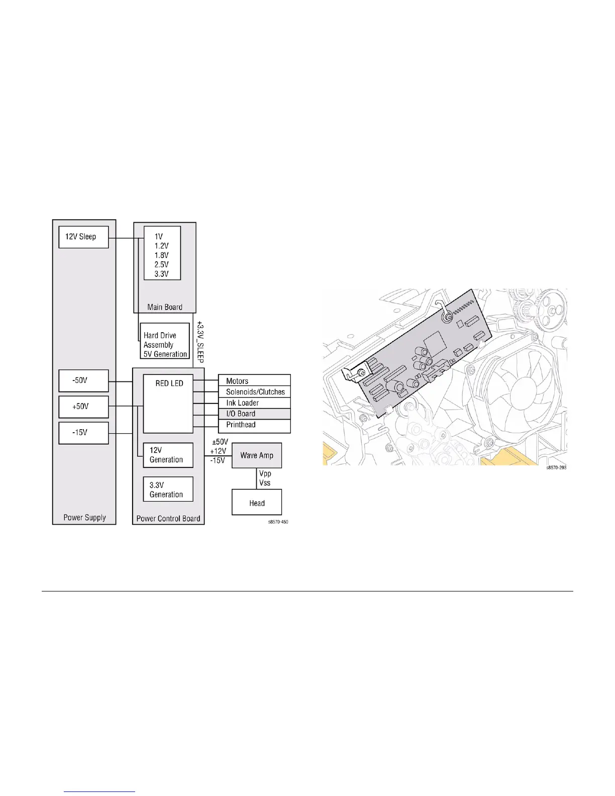
Voltage Supplies
The following diagram illustrates voltage generation for the boards in the Electronics Module.
Figure 10 Voltage Supplies
+3.3V Distribution
+3.3V_SLEEP DC is regulated on the Main Board. The power supply inputs +12V_SLEEP to
the Main Board. It is then passed through a switching regulator. The Power Control Board con
-
nects 3.3V to 3.3V_SLEEP with a switch when not in power saving modes.
+12V
The Power Supply delivers +50V to the Power Control Board. The Power Control Board uti-
lizes a switching regulator to generate +12V for the system.
I/O Board
All sensor and switch readings are input into the I/O Board. The I/O Board translates these
states into encoded information that it sends over a serial data bus (I/O Board Data Cable) to
the Electronics Module. The Electronics Module has no direct connection to the Sensors,
Switches, or Solenoids. In order to activate a Clutch or Solenoid, the Electronics Module sends
a command to the I/O Board, which processes the command and activates the appropriate
device.
Figure 11 I/O Board
 Loading...