6-6
LOWR
E
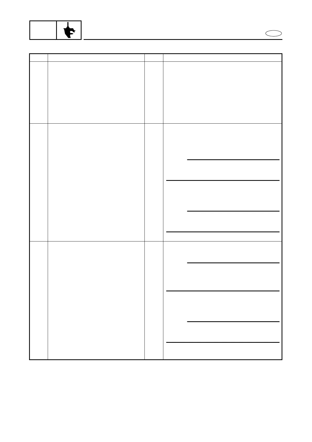
PROPELLER SHAFT AND REVERSE GEAR
REMOVAL AND INSTALLATION CHART
Step Procedure/Part name Q’ty Service points
PROPELLER SHAFT AND
REVERSE GEAR REMOVAL
Follow the left “Step” for removal.
Gear oil Refer to “LOWER UNIT” in chapter 3.
Propeller Refer to “LOWER UNIT REMOVAL”.
1 Flange bolt 2
2 Propeller shaft housing ass’y 1
3 Plane washer 1
4 Propeller shaft ass’y 1
PROPELLER SHAFT HOUSING
DISASSEMBLY
1
Reverse gear 1
2
Reverse gear shim *
3
Ball bearing 1
4
O-ring 1
5
O-ring 2
6
Oil seal 2
7
Needle bearing 1
8
Propeller shaft housing 1
PROPELLER SHAFT DISASSEMBLY
9
Cross pin ring 1
0
Cross pin 1
A
Shift plunger 1
B
Shift slider 1
C
Spring 1
D
Dog clutch 1
E
Propeller shaft 1
Reverse the removal steps for installation.
*: As required
NOTE:
Install the bearing with its manufacture’s
marks or numbers facing outward.
NOTE:
Install the bearing with its manufacture’s
marks or numbers facing outward.
NOTE:
By pushing the shift plunger, bring the
cross pin hole in the clutch dog with the
hole in the shift slider.
NOTE:
Install the clutch with “F” mark toward
the forward gear side.


 To Next Page