5-2
POWR
E
POWER UNIT REMOVAL
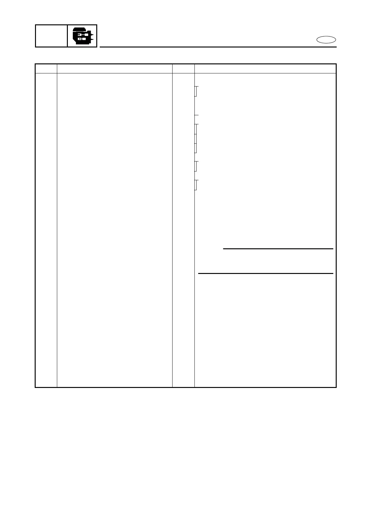
REMOVAL AND INSTALLATION CHART
Step Procedure/Part name Q’ty Service points
POWER UNIT REMOVAL
Follow the left “Step” for removal.
1 Bolt 1 M model
2 Engine stop switch lead (black) 1
3 Engine stop switch coupler (blue) 1
4 Maine switch lead coupler 1 E model
5 Oil level sensor lead coupler 1 EHTO model
6 Oil level warning lamp lead 1
7 Trim sensor lead coupler 1
8 Extension wire lead coupler 1
9 PTT motor lead 2 PTT model
10 PTT switch lead coupler 1
11 Choke lever rod 1 M model
12 Start-in-gear projection wire 1
13 Clip 1
14 Shift cable 1
15 Clip 1
16 Throttle cable 1
17 Bolt 2
18 Fitting plate ass’y 1
19 Pilot water hose 1
20 Fuel hose (Fuel joint - Fuel filter) 1
21 Bolt (with washer) 1 6
×
45 mm
22 Bolt (with washer) 1 6
×
20 mm
23 Screw 2
24 Apron 1
25 Bolt (with washer) 6
26 Bolt (with washer) 2 8
×
45 mm
27 Engine unit 1
28 Dowel pin 2
29 Upper case gasket 1
Reverse the removal steps for installation.
NOTE:
When installing the fitting plate, lift the
tiller handle straight up.