8-29
–+
ELEC
E
CHARGING SYSTEM
CHARGING SYSTEM PEAK VOLTAGE
1. Measure:
● Rectifier regulator input
Below specification → Lighting coil
measurement.
2. Measure:
● Lighting coil output
Beyond specification → Replace recti-
fier/regulator.
Below specification → Replace light-
ing coil.
FUSE
Refer to “STARTING SYSTEM”.
BATTERY
Refer to “GENERAL” in chapter 3.
Rectifier regurator input:
(electrical model)
8.5 V @ cranking
25 V @ 1,500 r/min
25 V @ 3,500 r/min
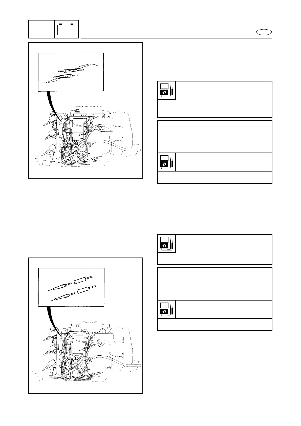
Measuring steps:
● Connect the tester to the rectifier/regu-
lator as shown.
● Set the tester dial to specification.
Range:
● Crank or start the engine.
Lighting coil output:
9.0 V @ cranking
25 V @ 1,500 r/min
25 V @ 3,500 r/min
Measuring steps:
● Connect the tester to the lighting coil
as shown.
● Set the tester dial to specification.
Range:
● Start the engine.
V
—
.......
V
—
.......


 To Next Page