5-14
POWR
E
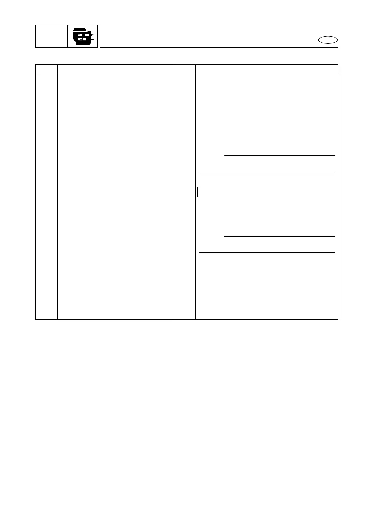
ELECTRICAL UNIT REMOVAL
REMOVAL AND INSTALLATION CHART
Step Procedure/Part name Q’ty Service points
ELECTRICAL UNIT REMOVAL Follow the left “Step” for removal.
1 Thermo switch coupler 2 Pink and black leads
2 Wire harness coupler 1
3 Electrothermal valve lead 1 Blue lead
4 Lighting coil lead 2 Green leads
5 CDI unit lead coupler 7
6 Bolt (with washer) 2
7 Fitting plate ass’y 1
8 Battery cable 1
9 Bolt (with washer) 2
10 PTT switch coupler 1 PTT model
11 PTT motor lead 2 Sky blue and light green leads
12 Bolt (with washer) 4 6 × 30 mm
13 Bolt (with washer) 1 8 × 25 mm
14 Electrical unit 1
15 Magneto control rod 1
16 Bolt (with washer) 2
17 CDI unit 1
18 Bolt 1
19 Magneto control lever 1
20 Spring 1
21 Accelation cam 1
Reverse the removal steps for installation.
Å: Setting length
NOTE:
Remove the battery cable at the grommet.
NOTE:
Disconnect the rod from the CDI unit.