4-6
FUEL
E
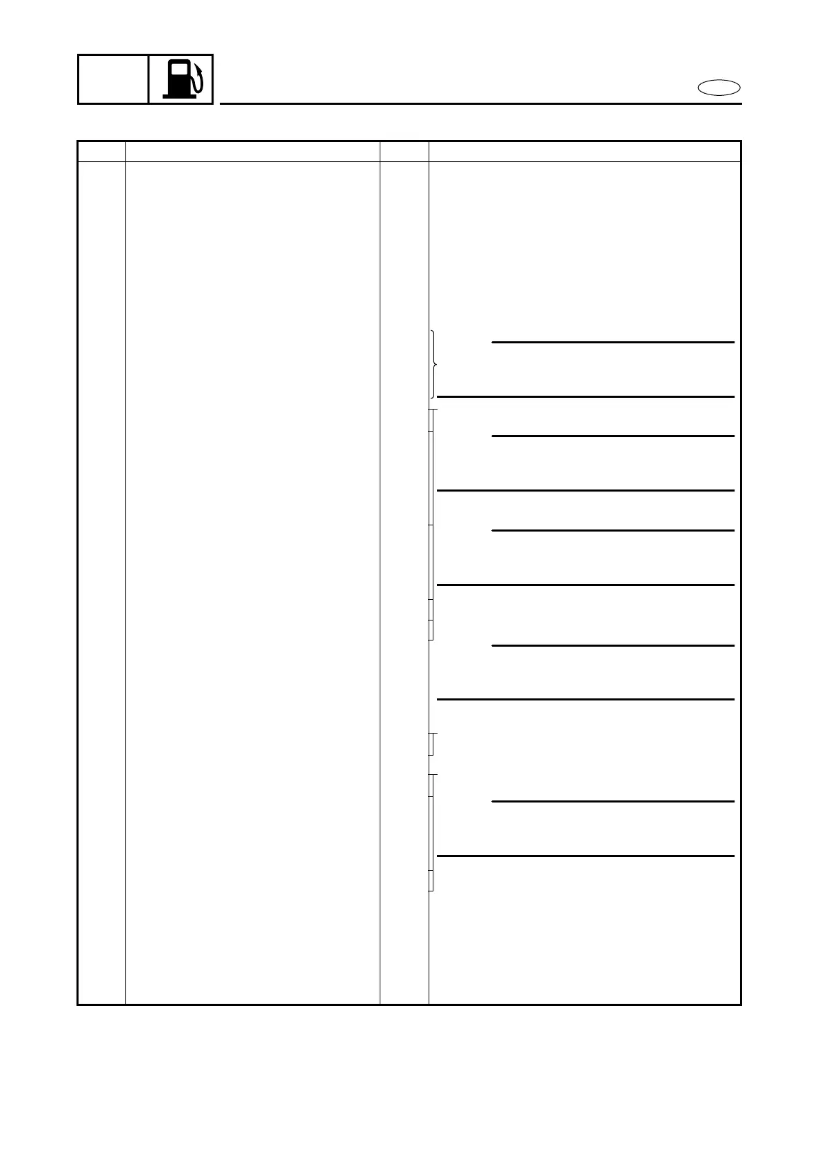
CARBURETOR REMOVAL
REMOVAL AND INSTALLATION CHART
Step Procedure/Part name Q’ty Service points
CARBURETOR REMOVAL
Follow the left “Step” for removal.
Oil tank ass’y Refer to “OIL TANK”.
1 Screw 2 6
×
40 mm
2 Screw 2 6
×
55 mm
3 Washer 4
4 Silencer 1
5 Seal 3
6 Clip 3
7 Fuel hose (joint pipe - cab.1) 1
8 Fuel hose (joint pipe - cab.2) 1
9 Fuel hose (joint pipe - cab.3) 1
10 Clip 1 E model
11 Pulser hose 1
12 Clip 1
13 Fuel enrichment hose 1
14 Bolt 1
15 Electrothermal valve lead (black) 1
16 Electrothermal valve lead (blue) 1
17 Accelerator lever rod 1
18 Oil pump link rod 1 Oil injection model
19 Link joint 1
20 Choke link rod 1 M model
21 Link joint 1
22 Choke lever joint 2
23 Link joint 4
24 Bolt 6 6
×
95 mm
25 Carburetor bracket 1
26 Carburetor ass’y 3
27 Gasket 3
Reverse the removal steps for installation.
NOTE:
Disconnect the hose at the carburetor
side.
NOTE:
Disconnect the hose at the carburetor
side.
NOTE:
Disconnect the hose at the intake mani-
fold side.
NOTE:
Disconnect the coupler at the lighting
coil.
NOTE:
After installing, check the smooth move-
ment of the choke knob.