2-11
SPEC
E
MAINTENANCE SPECIFICATIONS
Charge coil resistance Ω (color) 368 ~ 552 (Br — L)
Charging current (minimum)/rpm A/rpm 3/3,000
Charging current (maximum)/rpm A/rpm 5 ~ 7/5,500
Lighting voltage (minimum)/rpm V/rpm 12.0/3,000
Lighting voltage (maximum)/rpm V/rpm 13.5 ~ 16.5/5,500
Lighting coil resistance Ω (color) 0.56 ~ 0.84 (G/W — G)
Pole number 6
Charge coil output peak voltage
(minimum) (Br – L)
@ cranking V 145
@ 1,500 r/min V 160
@ 3,500 r/min V 130
Pulser coil output peak voltage
(minimum) (W/R, W/B, W/G – B)
@ cranking V 3.0
@ 1,500 r/min V 9.0
@ 3,500 r/min V 15.0
C.D.I unit output peak voltage
(minimum) (B/O, B/W, B/Y – B)
@ cranking V 125
@ 1,500 r/min V 140
@ 3,500 r/min V 110
Lighting coil output peak voltage
(minimum) (G – G/W)
@ cranking V 9.0
@ 1,500 r/min V 25
@ 3,500 r/min V 25
CDI UNIT:
Over revolution limiter revolution
limit
rpm 5,800 ~ 6,200
Over heat controlled revolution rpm 1,600 ~ 2,400
IGNITION COIL:
Type Single
Primary coil resistance Ω (color) 0.18 ~ 0.24 (B/W — B)
Secondarily coil resistance kΩ (color) 2.72 ~ 3.68 (B/W — High tension cord)
SPARK PLUG:
Gap mm (in) 0.9 ~ 1.0 (0.035 ~ 0.039)
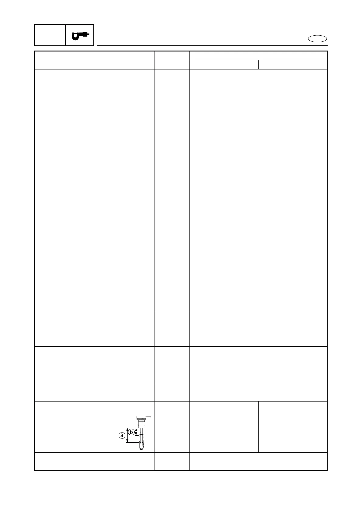
ENGINE OIL LEVEL SENSOR:
Electric starting
model
Manual starting
model
Float position lower a mm (in) 56.8 ~ 59.8
(2.24 ~ 2.35)
56.8 ~ 59.8
(2.24 ~ 2.35)
Float position high b mm (in) 32.8 ~ 35.8
(1.29 ~ 1.41)
—
OIL LEVEL WARNING LAMP:
Rating: V-mA 1.7-20 (Red)/ 2.2-20 (Yellow)/2.1-20 (Green)
Item Unit
Model
40 hp 50 hp