CRANKSHAFT AND BALANCER SHAFT
d. Put a piece of Plastigauge®
"1"
on
eac
h
cranksha
ft
journal.
TIP
~~~~~~~~~~~~~~
Do
no
t
put
the Plastigau
ge®
over the oil
ho
le in
the crankshaft journal.
!(.
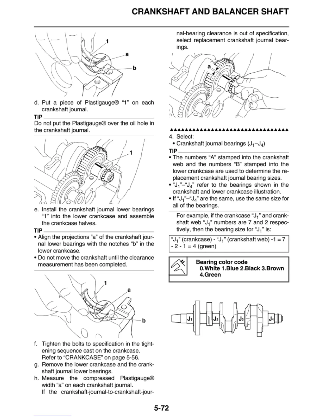
e. Install the crankshaft journal lower
bea
ri
ngs
"1" into the l
ower
crankcase
and
assemble
the crankcase halves.
TIP
~~~~~~~~~~~~~~-
• Align the projections "a" of the crankshaft jour-
na
l lower bearings with the notches "b" in the
l
ower
crankcase.
•
Do
not move the crankshaft unt
il
the clearance
measurement has been completed.
f. Tighten the bolts to specification in the tight-
ening sequence
cast
on the crankcase.
Refer to "CRANKCASE"
on
page 5-56.
g. Remove the l
ower
crankcase and the crank-
shaft journal lower bearings.
h.
Measure the compressed Plastigauge®
width
"a"
on each crankshaft journa
l.
If
the cranksha
ft
-journal-to-crankshaft-
jour
-
na
l-beari
ng
clearance is out
of
spec
ification,
se
lect replacement crankshaft journal bear-
ings.
••••••••••••••••••••••••••••••••
4.
Se
lect:
• Crankshaft journal bearings (J
1
-J
4
)
TI
P
~~~~~~~~~~~~~~-
• The numbers "A" stamped into the crankshaft
web
and the numbers "B" stamped into the
lower crankcase
are
used to determine the re-
placement crankshaft journal bearing sizes.
•
"J
1
"- "J
4
"
refer to the bearings shown in the
crankshaft
and
l
ower
crankcase illustration.
•If
"J
1
"-
"J
4
"
are the same, use the same size for
a
ll
of
the bearings.
For example, if the
cra
nk
case
"J
i"
and crank-
shaft
web
"Ji"
numbers are 7 and 2 respec-
tively, then t
he
bearing size for "J
1
"
is:
"J
1
"
(crankcase) - "J
1
"
(crankshaft web) -1 = 7
- 2 -
1 = 4 (green)
Bearing color c
od
e
O.Wh
ite 1.Blue 2.Black 3.Brown
4.Green
5-72
 Loading...