7.4 Trial Operation
7-21
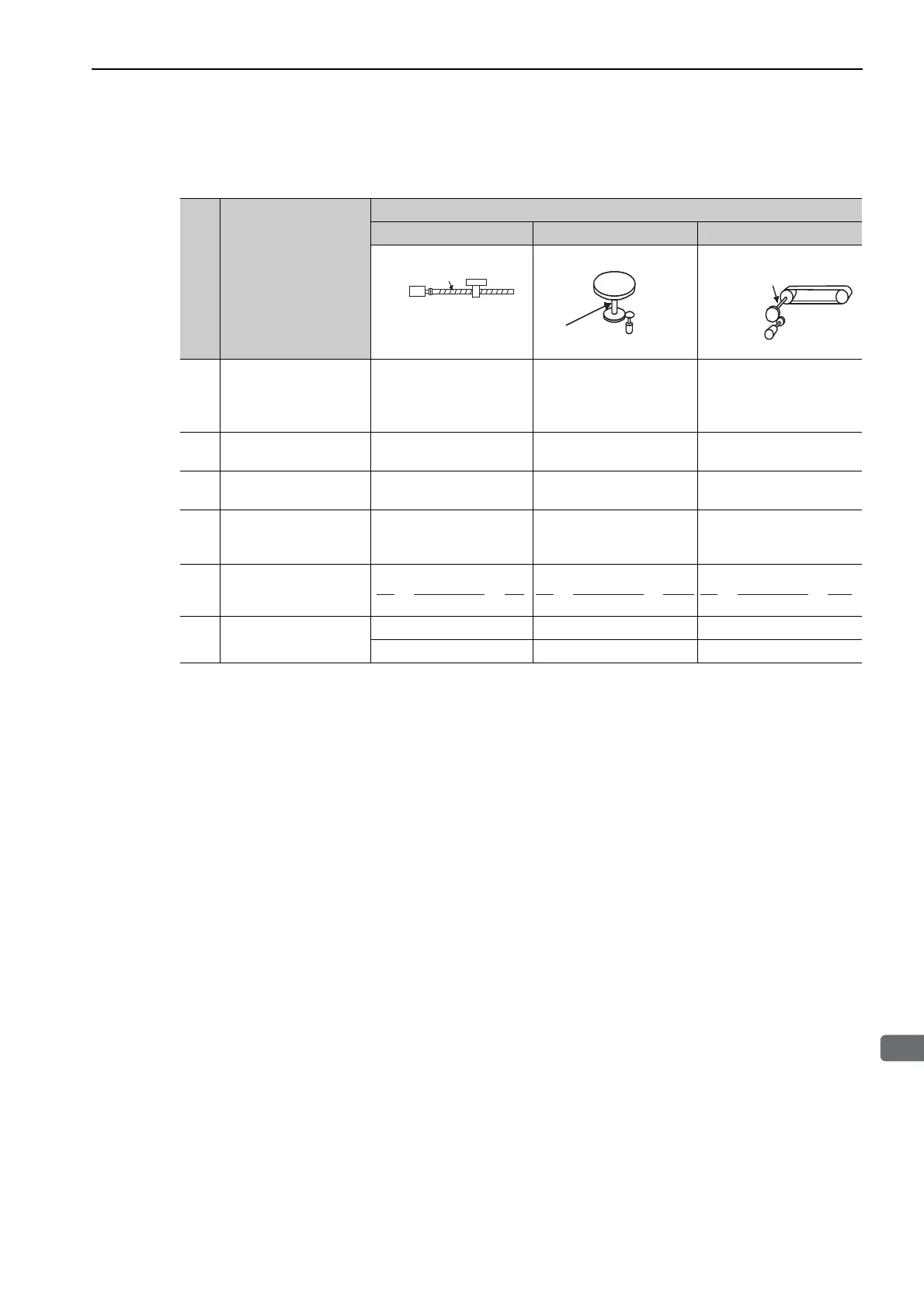
(2) Electronic Gear Ratio Setting Examples
The following examples show electronic gear ratio settings for different load configurations.
Step Operation
Load Configuration
Ball Screw Disc Table Belt and Pulley
1
Check machine specifi-
cations.
• Ball screw pitch: 6 mm
• Gear ratio: 1/1
Rotation angle per revolu-
tion: 360°
Gear ratio: 1/100
Pulley diameter: 100 mm
(pulley circumference: 314
mm)
• Gear ratio: 1/50
2
Check the encoder reso-
lution.
131072 (17-bit) 131072 (17-bit) 131072 (17-bit)
3
Determine the reference
unit used.
Reference unit: 0.001 mm
(1 μm)
Reference unit: 0.01°
Reference unit: 0.005 mm
(5 μm)
4
Calculate the travel dis-
tance per load shaft revo-
lution. (Reference unit)
6 mm/0.001 mm=6000 360°/0.01°=36000 314 mm/0.005 mm=62800
5
Calculate the electronic
gear ratio.
6 Set parameters.
PnA42: 131072 PnA42: 13107200 PnA42: 6553600
PnA44: 6000 PnA44: 36000 PnA44: 62800
Ball screw
pitch: 6 mm
17-bit encoder
Load shaft
Reference unit: 0.001 mm
17-bit encoder
Load shaft
Reference unit: 0.01
Gear ratio:
1/100
Load shaft
Gear ratio
1/50
Reference unit: 0.005 mm
Pulley diameter:
100 mm
17-bit encoder

 Loading...


