B.2 Setting Parameters
B-6
OW01 Mode Settings 1
Bit 0: Excessive Deviation Error Level Setting
0: Alarm, 1: Warning
√√−
Bits 1 to 2: Reserved for system. −−−
Bit 3: Speed Loop P/PI Switch
0: PI control, 1: P control
√√−
Bit 4: Switch Gain (Gain switch)
0: OFF, 1: ON
√√−
Bit 5: Switch Gain 2
*2
(Gain switch 2)
0: OFF, 1: ON
√√−
Bits 6 to F: Reserved for system. −−−
OW02 Mode Settings 2
Bits 0 to 7: Reserved for system. −−−
Bits 8 to F: Stop Mode Selection
0: Stop according to the Linear Deceleration
Rate/Deceleration Time Constant parameter
(Decelerate to a stop according to the linear
deceleration time constant).
1: Stop immediately. (Stop reference output.)
√√−
OW03
Function Set-
tings 1
Bits 0 to 3: Speed Unit Selection
0: Reference units/s (Reference unit/sec)
1: 10
n
reference units/min
2: Percentage of rated speed (1 = 0.01%)
3: Percentage of rated speed (1 = 0.0001%)
√√√
Bits 4 to 7: Acceleration/Deceleration Rate
Unit Selection
0: Reference units/s
2
1: ms
√√√
Bits 8 to B: Filter Type Selection
0: No filter (Filter none)
1: Exponential acceleration/deceleration filter
2: Moving average filter
√√√
Bits C to F: Torque Unit Selection
0: Percentage of rated torque (1 = 0.01%)
1: Percentage of rated torque (1 = 0.0001%)
√√√
OW04
Function Set-
tings 2
Bits 0 to 3: Latch Detection Signal Selection √√−
0: − −−−
1: − −−−
2: Phase-C pulse input signal √√−
3: /EXT1 √√−
4: /EXT2 √√−
5: /EXT3 √√−
Bits 4 to 7: External Positioning Signal Set-
ting
√√−
0: − −−−
1: − −−−
2: Phase-C pulse input signal √√−
3: /EXT1 √√−
4: /EXT2 √√−
5: /EXT3 √√−
Bits 8 to F: Reserved for system. −−−
Continued on next page.
*2. Currently under development.
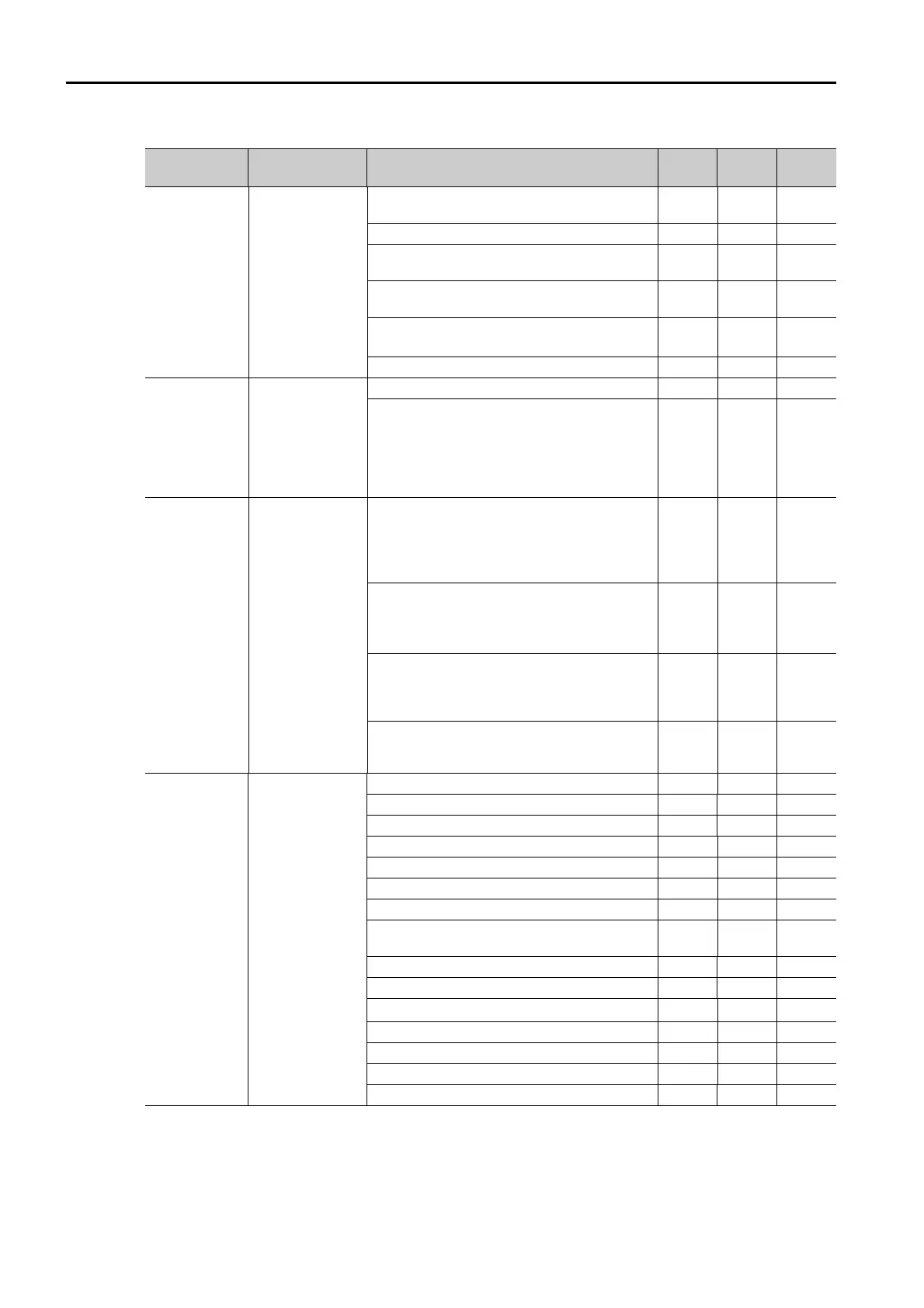
Continued from previous page.
Register
Address
Name Description SVB
SVC or
SVC32
SVR or
SVR32

 Loading...


