5.7 H: Terminal Functions
168 YASKAWA ELECTRIC SIEP C710606 44B YASKAWA AC Drive T1000V Technical Manual
Setting 7E: Forward Reverse Detection (V/f Control with Simple PG Feedback)
When a digital input is programmed for this function, the input determines the direction of the speed feedback signal for
V/f Control with PG feedback. If the input is open, the speed feedback signal is considered to be forward, if the input is
closed, it is considered to be in reverse. Refer to C5: Automatic Speed Regulator (ASR) on page 138 for details.
◆ H2: Multi-Function Digital Outputs
■ H2-01 to H2-03: Terminal MA, MB and MC, P1-C1 and P2-C2 Function Selection
The drive has three multi-function output terminals. Set parameters H2-01 to H2-03 between 0 and 192 to assign
functions to these terminals. Default values are listed in the following table.
Note: If not using an input terminal or if using it in the through-mode, be sure to set that terminal to “F”.
Table 5.17 Multi-Function Output Terminal Settings
Setting 0: During Run
Output closes when the drive is outputting a voltage.
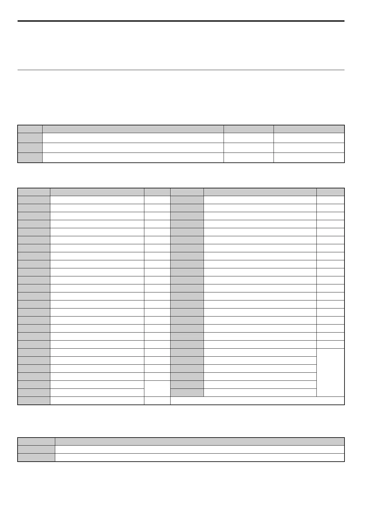
No. Parameter Name Setting Range Default
H2-01
Terminal MA, MB and MC Function Selection (relay)
0 to 152 E: Fault
H2-02
Terminal P1-C1 Function Selection (open-collector)
0 to 152 0: During Run
H2-03
Terminal P2-C2 Function Selection (open-collector)
0 to 152 2: Speed Agree 1
Setting Function Page Setting Function Page
0 During Run 168 1A During Reverse Operation 175
1 Zero Speed 169 1B During Baseblock (N.C.) 175
2 Speed Agree 1 169 1C Motor 2 Selection 175
3 User Set Speed Agree 1 169 1E Restart Enabled 175
4 Frequency Detection 1 170 1F Motor Overload Alarm (oL1) 175
5 Frequency Detection 2 170 20 Heatsink Overheat Pre alarm (oH) 175
6 Drive Ready 171 30 During Torque Limit 175
7 DC Bus Undervoltage 171 37 During Frequency Output 175
8 During Baseblock (N.O.) 171 39 Watt Hour Pulse Output 176
9 Frequency Reference Source 171 3C LOCAL/REMOTE Status 176
A Run Command Source 171 3D During Speed Search 176
B Torque Detection 1 (N.O.) 172 3E PID Feedback Low 176
C Frequency Reference Loss 172 3F PID Feedback High 176
D Braking Resistor Fault 172 4A During KEB Operation 176
EFault 172 4B During Short-Circuit Braking 176
F Not used/Through Mode 172 4C During Fast-stop 176
10 Alarm 172 50 Disturb Function Up 176
11 Reset Command Active 172 51 Disturb Function Enabled/Disabled 176
12 Timer Output 172 52 Uv during KEB 177
13 Speed Agree 2 172 100 to 10D Inverse Output of Setting 0 to D
177
14 User Set Speed Agree 2 173 10F to 11B Inverse Output of Setting F to 1B
15 Frequency Detection 3 173 11E to 120 Inverse Output of Setting 1E to 20
16 Frequency Detection 4 174 137, 138 Inverse Output of Setting 37 and 38
17 Torque Detection 1 (N.C.)
172
13C to 14C Inverse Output of Setting 3C to 4C
18 Torque Detection 2 (N.O.) 14F to 152 Inverse Output of Setting 14F to 152
19 Torque Detection 2 (N.C.) 172
Status Description
Open Drive is stopped.
Closed A Run command is input or the drive is during deceleration or during DC injection.

 Loading...


