12-20
IM 01E30D01-01EN
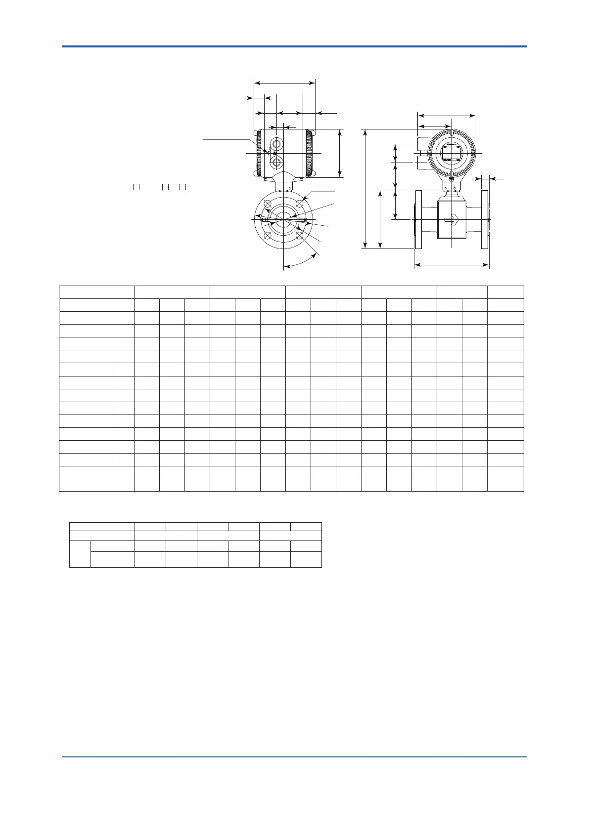
<12. OUTLINE>
●LayLengthCode1,AXR040-AXR065,JIS/ANSI/DINFlangeType
F1219.ai
*1: When indicator code N is selected, subtract 5 mm (0.2 inch) from the value in the figure.
*2: Depending on the selection of grounding ring code and optional code, add the following value to “L” (face-to-face length) and “t” (thickness of
flange).
Grounding Ring Code
S, L, H P, T N
None +0 +0
+26 (1.02)
+13 (0.51) -2 (0.08) -1 (0.04)
GA, GC, GD
+8
(0.31)
+4
(0.16)
(Special Gaskets)
+30 (1.18)
+15 (0.59) ― ―
Optional
Code
BJ1 (JIS10K)
BJ2 (JIS20K)
200
(7.87)
140
(5.51)
20
(0.79)
41
(1.61)
105
(4.13)
45
19
(0.75)
4
138
(5.43)
68
(2.67)
299
(11.79)
7.5
(16.5)
200
(7.87)
155
(6.10)
20
(0.79)
53
(2.09)
120
(4.72)
45
19
(0.75)
4
157
(6.16)
79
(3.11)
318
(12.52)
8.7
(19.2)
200
(7.87)
175
(6.89)
22
(0.87)
66
(2.60)
140
(5.51)
45
19
(0.75)
4
176
(6.93)
89
(3.50)
338
(13.31)
11.0
(24.2)
040
40
(1.5)
A
050
50
(2)
A
065
65
(2.5)
A
040
40
(1.5)
A
050
50
(2)
A
065
65
(2.5)
A
040
40
(1.5)
A
050
50
(2)
A
065
65
(2.5)
A
040
40
(1.5)
A
050
50
(2)
A
065
65
(2.5)
A
040
40
(1.5)
A
050
50
(2)
A
065
65
(2.5)
A
200
(7.87)
140
(5.51)
22
(0.87)
41
(1.61)
105
(4.13)
45
19
(0.75)
4
138
(5.43)
68
(2.67)
299
(11.79)
8.0
(17.6)
200
(7.87)
155
(6.10)
22
(0.87)
53
(2.09)
120
(4.72)
22.5
19
(0.75)
8
157
(6.16)
79
(3.11)
318
(12.52)
8.9
(19.6)
200
(7.87)
175
(6.89)
24
(0.94)
66
(2.60)
140
(5.51)
22.5
19
(0.75)
8
176
(6.93)
89
(3.50)
338
(13.31)
11.3
(24.9)
200
(7.87)
127.0
(5.00)
21.5
(0.85)
41
(1.61)
98.6
(3.88)
45
15.7
(0.62)
4
131
(5.17)
68
(2.67)
293
(11.53)
7.2
(15.8)
200
(7.87)
152.4
(6.00)
23.1
(0.91)
53
(2.09)
120.7
(4.75)
45
19.1
(0.75)
4
155
(6.11)
79
(3.11)
317
(12.47)
9.3
(20.5)
200
(7.87)
177.8
(7.00)
26.4
(1.04)
66
(2.60)
139.7
(5.50)
45
19.1
(0.75)
4
177
(6.97)
89
(3.50)
339
(13.35)
12.8
(28.2)
200
(7.87)
155.4
(6.12)
24.6
(0.97)
41
(1.61)
114.3
(4.50)
45
22.4
(0.88)
4
146
(5.73)
68
(2.67)
307
(12.09)
9.6
(21.1)
200
(7.87)
165.1
(6.50)
26.4
(1.04)
53
(2.09)
127.0
(5.00)
22.5
19.1
(0.75)
8
162
(6.36)
79
(3.11)
323
(12.72)
10.9
(24.0)
200
(7.87)
190.5
(7.50)
29.4
(1.16)
66
(2.60)
149.4
(5.88)
22.5
22.4
(0.88)
8
184
(7.24)
89
(3.50)
346
(13.62)
14.6
(32.2)
200
(7.87)
150
(5.91)
22
(0.87)
41
(1.61)
110
(4.33)
45
18
(0.71)
4
143
(5.63)
68
(2.67)
304
(11.98)
8.7
(19.1)
200
(7.87)
165
(6.50)
24
(0.94)
53
(2.09)
125
(4.92)
45
18
(0.71)
4
162
(6.36)
79
(3.11)
323
(12.72)
10.6
(23.4)
200
(7.87)
185
(7.28)
22
(0.87)
66
(2.60)
145
(5.71)
45
18
(0.71)
4
181
(7.13)
89
(3.50)
343
(13.50)
11.8
(26.0)
Size code
Process Connection
Size
Lining code
0
-3
Face-to-face length
Outside dia.
Thickness
Inter diameter of
Grounding ring
Weight kg (lb)
L
øD
t *
2
ød
Pitch circle dia. øC
Bolt hole interval θ°
Hole dia. øh
Number of holes N
Height H1
Height H2
Max. Height Hi
*
2
BA1 (ANSI Class 150) BA2 (ANSI Class 300)
BD4 (DIN PN40)
BD2 (DIN PN16)
L t L t L t
Unit: mm (approx. inch)
AXR040
AXR050
AXR065
G
C
1
1
2
1
2
2
4
A 1
B
B
B
B
B
B
J
J
A
A
D
D
1
18.5(0.73)
90(3.54)
164 (6.46)
*1
33
*1
(1.30)
L
*2
t
*2
154 (6.06)
28
(1.10)
33
(1.30)
70(2.76)
Hi
H1
(H2)
73
(2.87)
49
(1.93)
θ°
Ground Terminal
(M4)
N-
ø
h
ø
D
ø
C
(
ø
d)
ø128 (5.04)

 Loading...

