Installation 2 - 9
Serial Host Connection
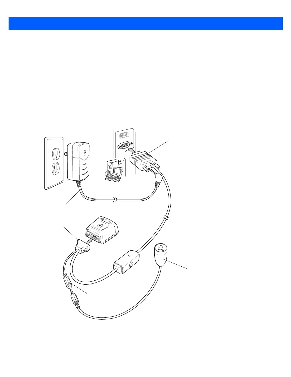
1. Plug the 9-pin D-connector with the end marked SCANNER into the DS457. See Serial Interface Cable
Connection on page 2-10 to determine which cable to use.
2. If using an external switch and applicable host cable, plug the trigger cable into the female stereo
connector on the flying lead of the 9-pin D-connector. See Figure 2-10 on page 2-10 for connector pins.
3. Plug the host connector into the appropriate port on the host.
4. Plug the power supply into an AC receptacle, and the output cable from the power supply into the
connector near the host end of the interface cable.
5. Check all connections to ensure they are secure.
6. Program the DS457 using the programming bar codes in this guide.
Figure 2-9
Serial Connection
Trigger or Photo
Sensor (Optional)
Host Connector
Trigger Jack (Optional)
See Figure 2-10
9-pin D-connector
Power Supply