Specifications
202
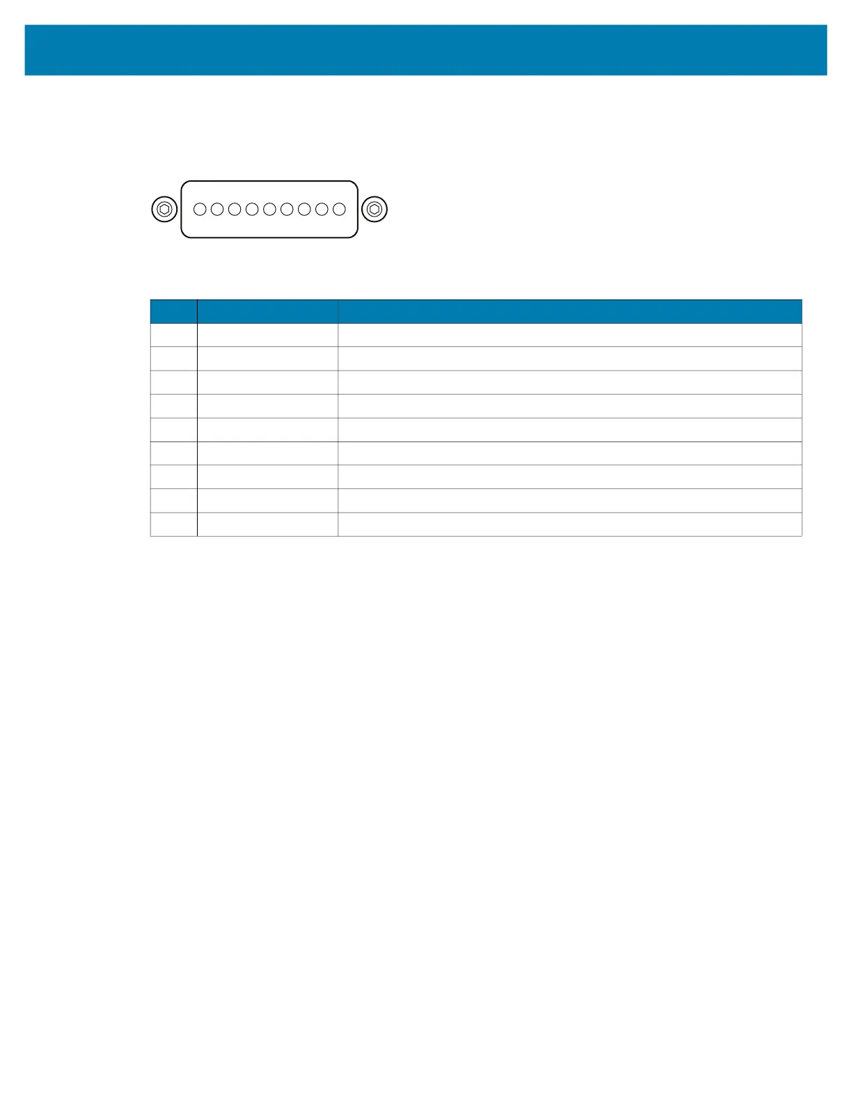
I/O Connector Pin-Outs
Table 31 I/O Connector Pin-Outs
Pin Signal Description
1 Ground Ground pin connected to the Cradle or USB Charge Cable ground.
2 USB D- USB OTG data signal negative.
3 USB D+ USB OTG data signal positive.
4 USB PWR Power supply from USB Charging Cable.
5 Batt_Det_C Connected with 1k Ω resistor to Ground in the battery pack.
6 Cradle_PWR DC Power supply from the Cradle.
7 USB_CC2 Used by USB_CC2 following USB type-C specification for USB 2.0.
8 USB_CC1 Used by USB_CC1 following USB type-C specification for USB 2.0.
9 GND Ground pin connected to the Cradle or USB Charge Cable ground.
P9 P1
 Loading...
