1-26
Pioneer Gold 3.00 Controller Technical Guide
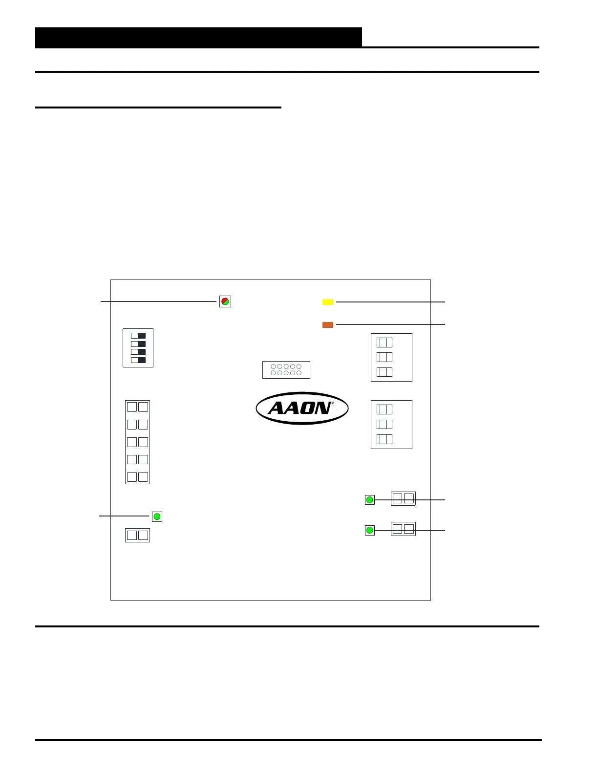
Using LEDs To Verify Operation
The Pioneer Gold Electric Heat Board is equipped with LEDs
that can be used to verify operation and perform troubleshooting.
See Figure 1-15, this page, for the LED locations. The LEDs
associated with these outputs allow you to see what is active
without using a voltmeter. The LEDs and their uses are as follows:
Operation LEDs
POWER: This green LED will light up and stay on solid to
indicate that 24 VAC power has been applied to the board.
STATUS: If solid green, the Limit Switch input/safety is closed.
If the LED turns red, the Limit Switch input/safety is open.
MODBUS LEDs
D2: This yellow LED will light up and blink continuously to
indicate there is MODBUS communications.
D3: This orange LED will light up and blink continuously to
indicate there is MODBUS communications.
Output LEDs
HEAT 1 - Electric Heat Stage 1 LED: This green LED will light
up when the Electric Heat Stage 1 relay is active.
HEAT 2 - Electric Heat Stage 2 LED: This green LED will light
up when the Electric Heat Stage 2 relay is active.
Figure 1-13: Pioneer Gold Electric Heat Board LED Locations
HEAT STAGE 1 LED
HEAT STAGE 2 LED
D2 LED
D3 LED
STATUS LED
POWER LED
A-
S
B+
SW1
HEAT1
HEAT2
POWER
STATUS
J4
J6
A-
S
B+
J1
J3
J2
J7
J5
MODBUSMODBUS
TROUBLESHOOTING
Electric Heat Board Diagnostics