1-28
Pioneer Gold 3.00 Controller Technical Guide
Type III 10K Ohm Temp Sensor
Testing
The following sensor voltage and resistance table is provided to
aid in checking sensors that appear to be operating incorrectly.
Many system operating problems can be traced to incorrect sensor
wiring. Be sure all sensors are wired per the wiring diagrams in
this manual.
If the sensors still do not appear to be operating or reading
sensor is operating correctly per the tables. Please follow the
notes and instructions that appear after the chart when checking
sensors.
Thermistor Sensor Testing Instructions
Use the resistance column to check the thermistor sensor while
disconnected from the controllers (not powered).
Use the voltage column to check sensors while connected to
powered controllers. Read voltage with meter set on DC volts.
Place the “-” (minus) lead on GND terminal and the “+” (plus)
lead on the sensor input terminal being investigated.
If the voltage is above 3.05 VDC, then the sensor or wiring is
“open.” If the voltage is less than 0.18 VDC, then the sensor or
wiring is shorted.
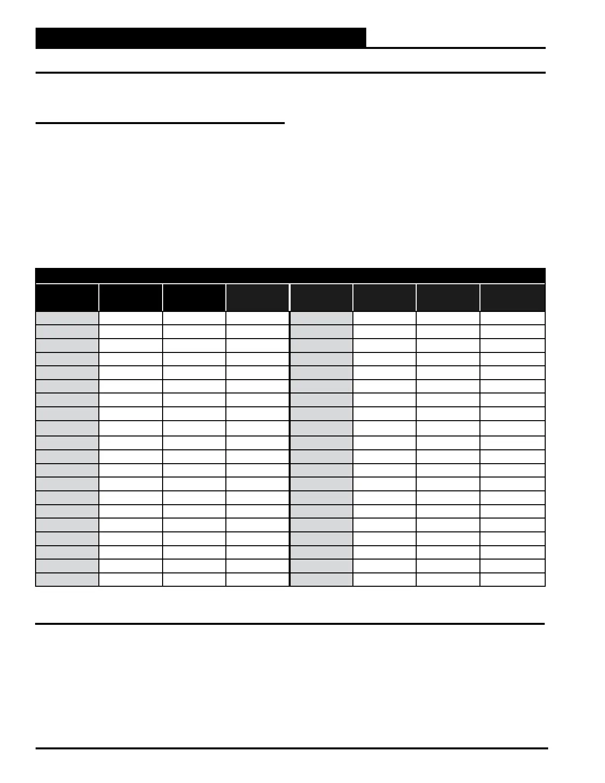
Temperature – Resistance – Voltage for Type III 10K ohm Thermistor Sensors
Temp (ºF) Temp (ºC)
Resistance
(Ohms)
Voltage @
Input (VDC)
Temp (ºF) Temp (ºC)
Resistance
(Ohms)
Voltage @
Input (VDC)
-10 93333 66
-5 3 68
0 69
5 70
10 71
15 -9.4 72
20 73
25 -3.9 74
30
75
35 76
40 4.4 77
45 78
50 80
52 82
54 84
56 86
58 88
60 90
62 95
64 100
NOTE:
Table 1-10: Temperature/Resistance for Type III 10K ohm Thermistor Sensors
TROUBLESHOOTING
Temperature Sensor Testing