3-12
Pioneer Gold 3.00 Controller Technical Guide
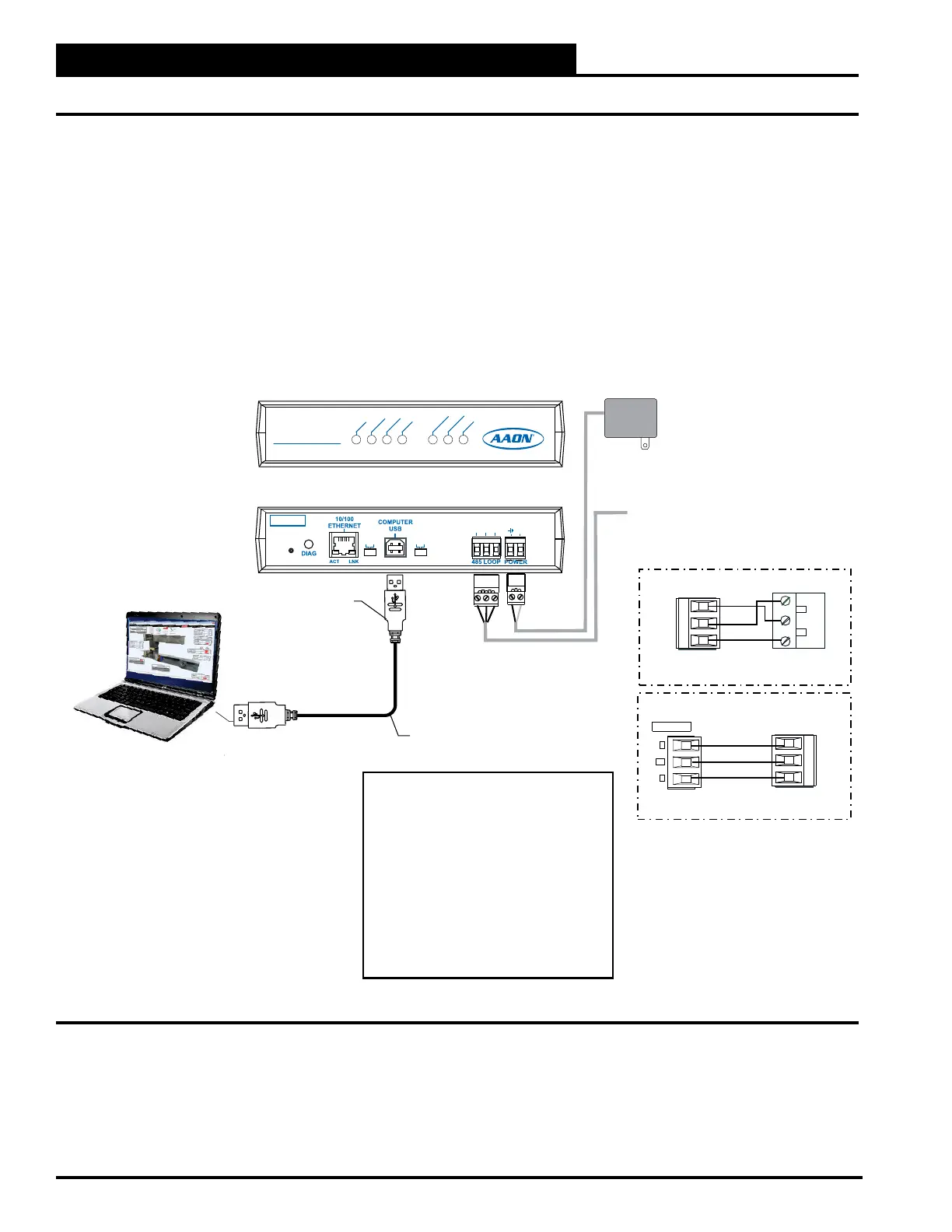
CONNECTIONS
CommLink 5 Connection
USB cable assembly
(supplied with CommLink 5)
Type A USB
Cable End
Type B USB
Cable End
Job-Site Computer (by others)
with Prism 2 Software installed
110 VAC to 24 VAC
Power Pack
(Supplied With CommLink 5)
Connect To MiniLink PD network terminals
(when used). Otherwise, connect to Pioneer
Gold Controller communications terminal
BACNET
Connect Type A cable end to USB port on
computer and Type B end to USB port on
CommLink 5.
(Front View)
CommLink 5
(Back View)
CommLink 5
Wiring To Be R To B+,
SHLD (G) To S (G) & T- To A-
S
A-
B+
Pioneer GoldCommLink 5
Wiring Should Be R To R,
SH (G) To Shld (G) & T To T-
MiniLink PD 5 CommLink 5
NETWORK
T
SH
R
CommLink 5
COMM USB NETWORK
LOOP
TX-USB
RX-USB
COMP
ACT-LAN
LNK-LAN
WLAN
MULTIPLE
HIGH
SINGLE
LOW
BAUD
R (+)
SHLD
T (-)
SERIAL #
24VAC
GND
LOOP
SOFTWARE
T (-)
SHLD
R (+)
T (-)
SHLD
R (+)
NOTES:
USB drivers supplied with the CommLink 5
must be installed on the connected computer
before the CommLink 5 can be used.
Set CommLink internal switch to “Multi” when
MiniLink PD is used. Otherwise, switch must be
set to “Single”.
WattComm must be selected as the Protocol
in the Pioneer Gold Touchscreen’s Network
Screen in order to establish a connection with
Prism 2.
The Pioneer Gold Controller functions in "High"
baud.
Figure 3-22: CommLink 5 Connection