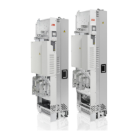
2. Install the telescopic extraction and insertion ramp to the cabinet base with two
screws.
3. Remove the upper and lower left-hand side front covers of the drive module (M4×8
combi screws, 2 N·m [18 lbf·in]).
4. Attach the drive module lifting lugs to the enclosure frame with chains.
5. Push the drive module carefully into to the enclosure preferably with the help from
another person.
6. Attach the grounding busbar that has been previously attached to the input cabling
panel to the drive module.
Note: The design of the grounding busbar can be different from what is shown
in the figure.
7. Connect the busbars of the drive module to the busbars of the cabling panels
(M12 combi screw, 70 N·m [52 lbf·ft]).
126 Installation example with full cabling panels (option +H381)

 Loading...