Accessories
120
3ADW000194R0611 DCS800 Hardware Manual f us
Diagramm
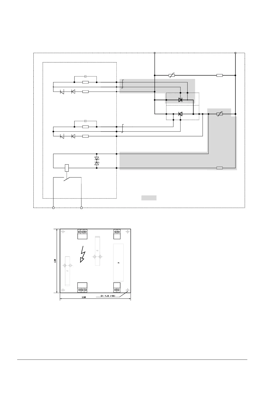
Overvoltage Protection DCF 505 / DCF 506
Layout of SDCS-FEP-1/FEP-2
There are two trigger units in use:
- SDCS-FEP-1 for systems, used at line voltages up to 500 V; this board is equipped with a 1400 V
trigger diode.
- SDCS-FEP-2 for systems, used at line voltages up to 690 V; this board is equipped with a 1800 V
trigger diode.
F
-
A1
X2:3
X1:1
G1
A
K1
X2:2
X1:3
X2:1
G2
K2
X3:1
X3:2
X4:1
X4:2
K
R3
F
+
X11 X12
12AK
12
12
12
R1
R4
R2
V1
X1:2
SDCS-FEP-1 (500 V)
SDCS-FEP-2 (690 V)
DCF505di_d.dsf
parts not built-in at 2-Q unit, R3 jumpered
red
grey
red
grey
X3
X4X2
X1
line potential !
SDCS-FEP-1/FEP-2
Fep1_2.dsf
Output X4:1-2
Potential isolated by relay (NO contact)
Contacts no protected
Contact rating: AC:
≤ 60 V~/ ≤ 50 mA~
DC:
≤ 60V-/ ≤ 50 mA-
 Loading...


