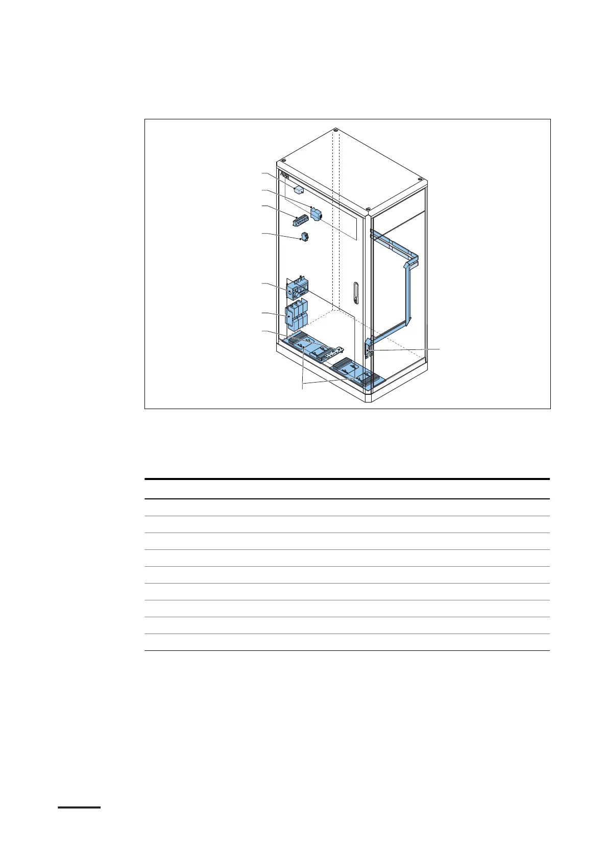
3.5.2 Power cabinet, inside
A DC output busbars
B Cable inlets
C PE busbar
D AC power connector
E Main switch
F X-10 terminal block
G X-8 terminal block
H CAN2FIBER device
I Tilt sensor (option)
Part Function
DC output busbar To connect the DC output power cables
Cable inlet A plate with openings for cables
PE busbar To connect PE cables
AC power connector To connect to the AC input power cable
Main switch To connect or disconnect the AC power
X-10 terminal block To connect to the AC auxiliary power cable
X-8 terminal block To connect the interlock, DC guard, and CAN cables
CAN2FIBER device To connect the optical CAN cable
Tilt sensor (option) To detect the tilt of the power cabinet
Description
22 9AKK107992A6488-EN | 004