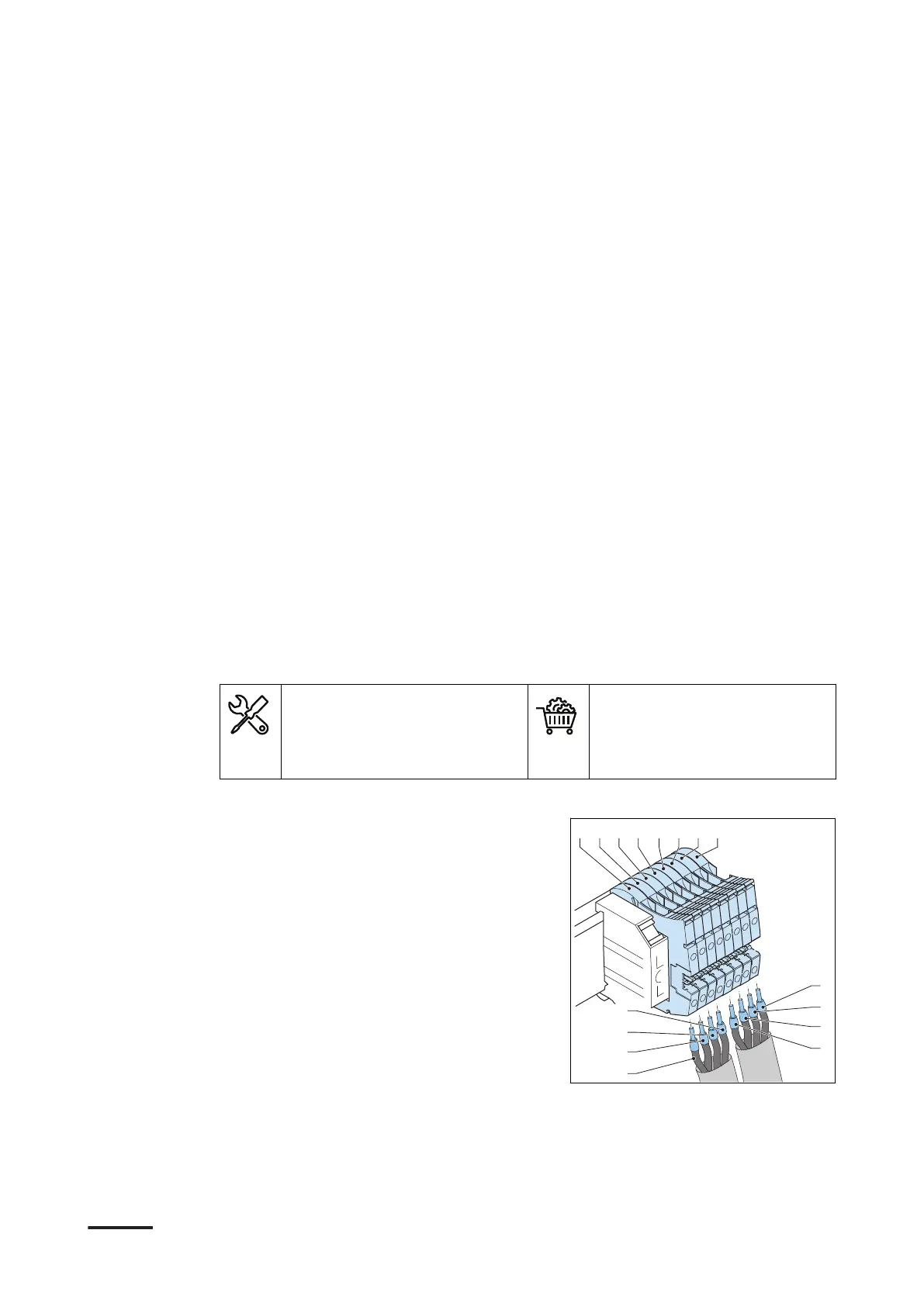
4. Connect these wires:
•
V+
wire (A) from the external customer interface, wire number 1, to the
terminal X1-1 (I)
•
V+
wire (B) from the secondary power cabinet, wire number 1, to the terminal
X1-2 (J)
•
V-
wire (C) from the external customer interface, wire number 2, to the
terminal X1-3 (K)
•
V-
wire (D) from the secondary power cabinet, wire number 2, to the terminal
X1-4 (L)
•
Rin
wire (E) from the external customer interface, wire number 3, to the
terminal X1-5 (M)
•
Rin
wire (F) from the secondary power cabinet, wire number 3, to the
terminal X1-6 (N)
•
Rout
wire (G) from the external customer interface, wire number 4, to the
terminal X1-7 (O)
•
Rout
wire (H) from the secondary power cabinet, wire number 4, to the
terminal X1-8 (P)
5. Tighten the screws to the correct torque. For the specification, refer to section
12.14.
7.9 Connect the control cable for the tilt sensors to the
secondary power cabinet (option)
Preliminary requirements
• Torque screwdriver, cross
• Wire cutter
• Wire stripper pliers
• Crimp pliers
• Control cable for the tilt
sensors. Refer to section
12.19.7.
• Ferrules
Procedure
1. Strip the insulation from the ends of
the wires (A) to (H). For the
specification, refer to section 12.19.7.
2. Crimp ferrules onto the end of the
wires.
3. Loosen the screws of the terminal
block X-1.
Electrical installation of the power cabinet
9AKK107992A6488-EN | 004 53