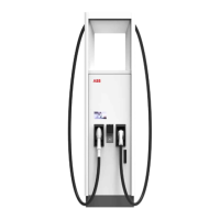
3.5.5 Charge post CP500 Generation 3, inside
A Cooling unit
B DC power busbars
C Cable gland plates
D PE busbar
E Q1 RCD
F X-10 terminal block
G X-20 terminal block
H CAN2FIBER device
Part Function
Cooling unit To decrease the temperature of the charge cables
DC power busbars To connect the DC power cables
Cable gland plates Glands for the cables to the charge post
PE busbar To connect the PE wire
Q1 RCD Residual current circuit breaker to connect or discon-
nect the AC auxiliary power to the charge post
X-10 terminal block To connect the AC auxiliary power cable
X-20 terminal block To connect the interlock and DC guard cable
CAN2FIBER device To connect the optical CAN cable
Description
24 9AKK107992A6488-EN | 004
 Loading...