Preliminary requirements
• Optical CAN cable. Refer to
section 12.19.6
• Cable tie
•
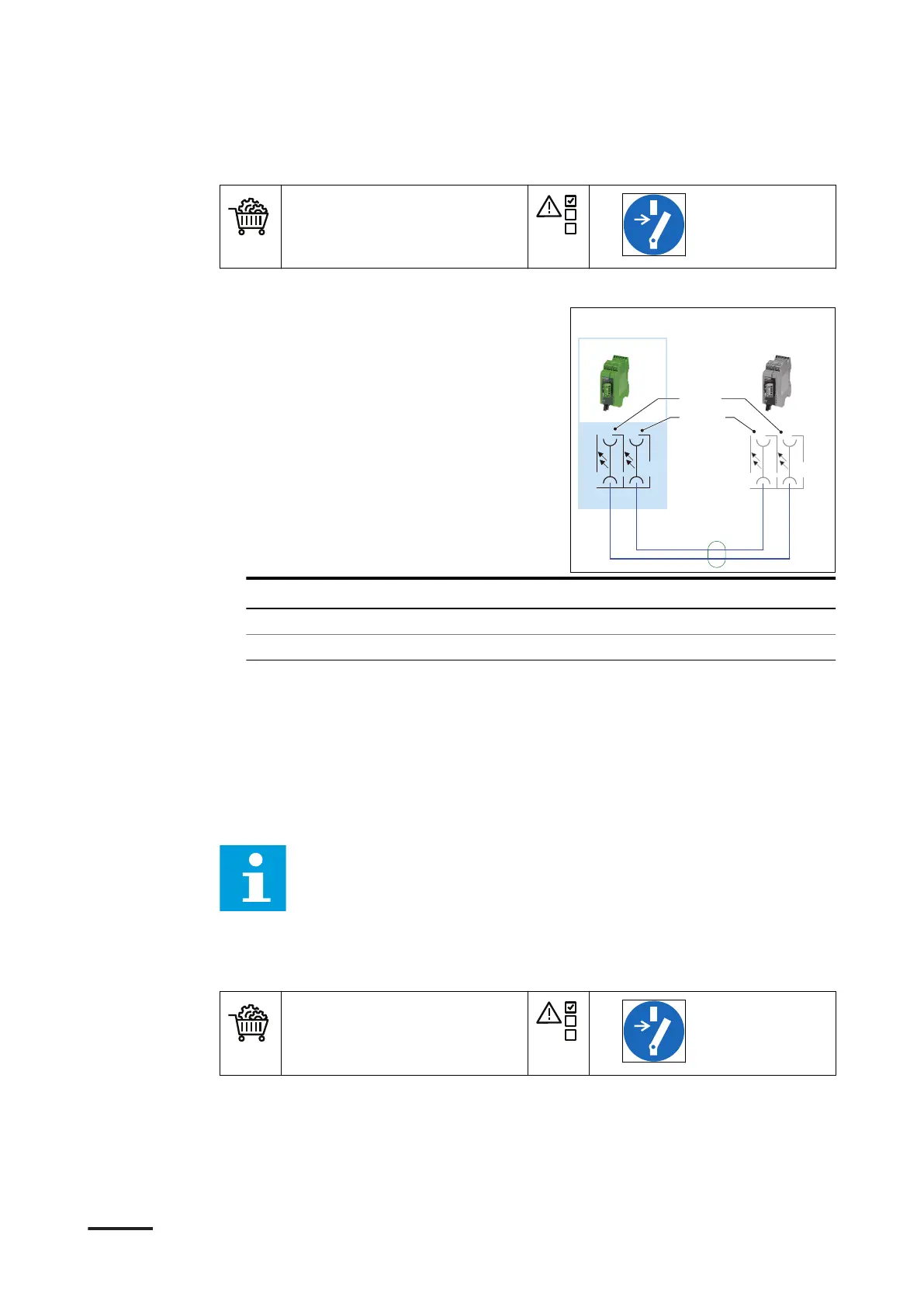
Procedure
1. Guide the optical CAN cables to the
fibre-optics converter.
2. Remove the protection covers from
the optical connectors.
3. Connect the wires as mentioned in the
below table.
• Use the illustration as a reference.
• For the optical CAN cable
specifications, refer to section
12.19.6.
Wire from charge post
Connect to primary power cabinet
(A) CAN bus fiber cable Rx (C) connection Tx at D2
(B) CAN bus fiber cable Tx (D) connection Rx at D2
4. Tie the CAN cables together.
a. Tighten the loops of the cables with cable ties.
b. Make sure that the loop bend radius is sufficient, to prevent damage to the
cable core. For the specification, refer to section 12.19.6.
7.7.2 Connect the analog CAN cables between the primary and secondary
power cabinet
Note:
• Use the illustration below as a reference.
• For the connection procedure, refer to section 11.
• For a detailed overview of all electrical connections, refer to section
12.20.
Preliminary requirements
• CAN cables. Refer to section
12.19.6
• Cable tie
•
TX
RX
A100
D2
Power cabinet Charge post
TX
RX
AC
D B
Electrical installation of the power cabinet
50 9AKK107992A6488-EN | 004