Procedure
1. Prepare ferrules for the wires that are mentioned below. Refer to section 11.2.
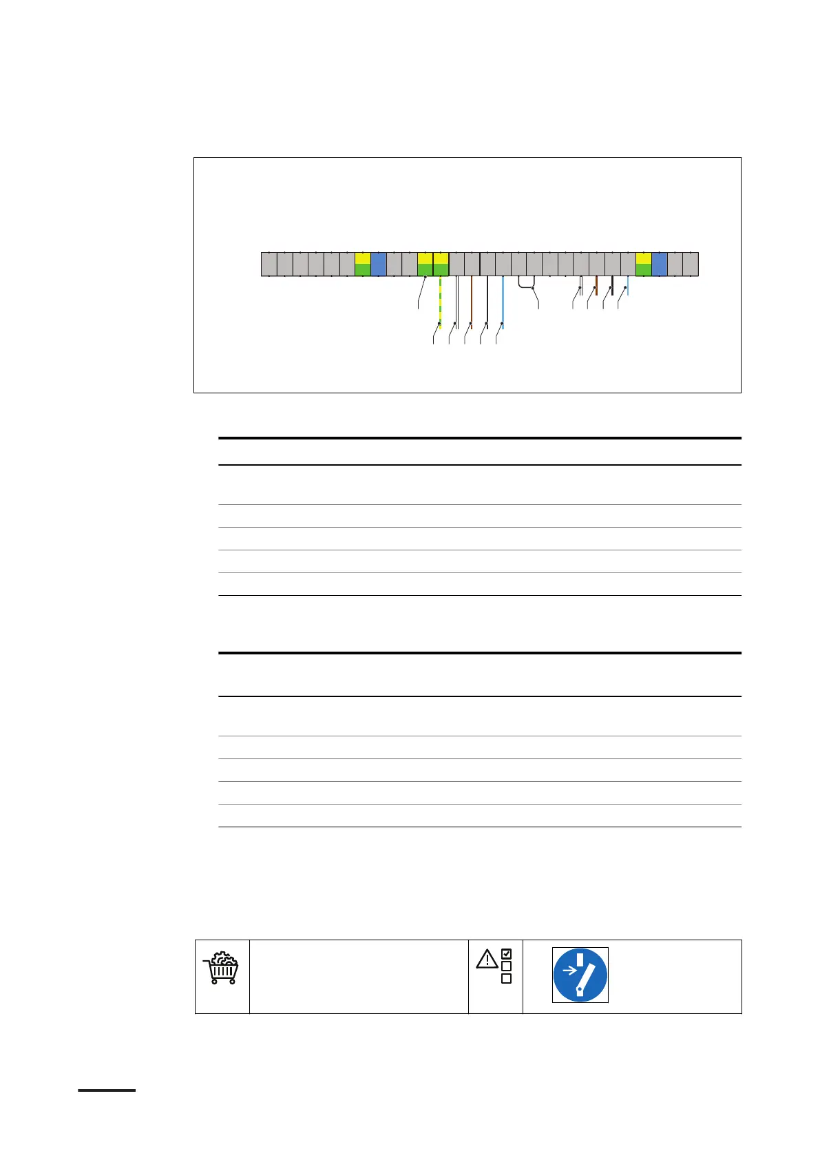
2. Connect these wires from the charge post:
Wire from charge post
Connect to terminal Terminal name
(A) Ground wire or shield
mesh
Earthing terminal PE
(B) Interlock IN X8-15 IL OUT 1
(C) Interlock OUT X8-14 IL IN 1
(D) DC guard GND X8-13 DC guard A1 GND
(E) DC guard signal X8-12 DC guard A1
3. Connect a wire loop (F) between the terminals X8-10 and X8-11.
4. Connect these wires from the secondary power cabinet:
Wire from secondary
power cabinet
Connect to terminal Terminal name
(G) Ground wire or shield
mesh
Earthing terminal PE
(H) IL IN 1 X8-7 IL OUT 3
(I) IL OUT 1 X8-6 IL IN 3
(J) DC guard B GND X8-5 DC guard B GND
(K) DC guard B X8-4 DC guard B
7.6.2 Connect the interlock and DC guard cables to the secondary power
cabinet
Preliminary requirements
• Interlock and DC guard
cables. Refer to section
12.19.5
•
18 17 16192122 2024 23 15 14 13 12
11
10
9 8 7 6 5 4
-X8
123
CanH_IN
GND_CAN_IN
CanL_IN
DC-Guard B
DC-Guard B GND
IL_IN_3
IL_OUT_3
DC-Guard A 2
DC-Guard A 2 GND
IL_IN_2
IL_OUT_2
DC-Guard A 1
DC-Guard A 1 GND
IL_IN_1
IL_OUT_1
CanH_OUT
CanL_OUT
GND_CAN_OUT
Internal USE
Internal USE
Internal USE
Internal USE
Internal USE
Internal USE
PE
PE
PE
PE
A
G H I J K
B C D E
F
Electrical installation of the power cabinet
48 9AKK107992A6488-EN | 004