3. Connect the wires to the secondary power cabinet:
a. Loosen the terminal screws on X8-16, X8-17, and X8-18 of the secondary
power cabinet.
b. Connect the wires:
Wire from primary
power cabinet
Connect to secondary
power cabinet
Terminal name
(A) CAN H X8-16 CANH OUT
(B) CAN L X8-17 CANL OUT
(C) CAN shield X8-18 GND CAN OUT
c. Tighten the screws to the correct torque. For the specification, refer to
section 12.14.
4. Tie the CAN cables together.
a. Tighten the loops of the cables with cable ties.
b. Make sure that the loop bend radius is sufficient, to prevent damage to the
cable core. For the specification, refer to section 12.19.6.
7.8 Connect the control cable for the tilt sensors to the
primary power cabinet (option)
Preliminary requirements
• Torque screwdriver, cross
• Wire cutter
• Wire stripper pliers
• Crimp pliers
• Control cable for the tilt
sensors. Refer to section
12.19.7.
• Ferrules
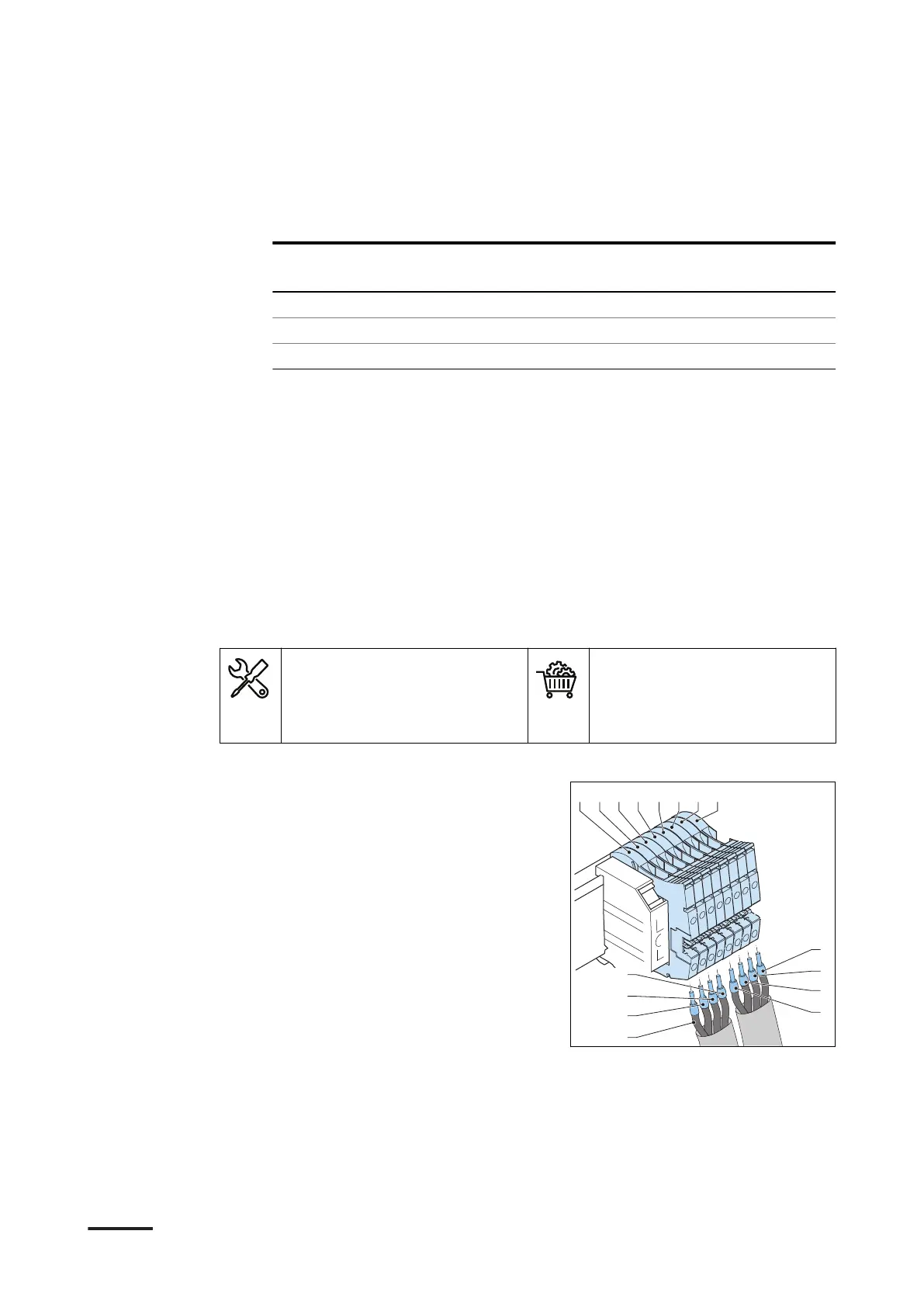
Procedure
1. Strip the insulation from the ends of
the wires (A) to (H). For the
specification, refer to section 12.19.7.
2. Crimp ferrules onto the end of the
wires.
3. Loosen the screws of the terminal
block X-1.
Electrical installation of the power cabinet
52 9AKK107992A6488-EN | 004
 Loading...