Procedure
1. Strip the insulation from the ends of
the wires (A) to (D).
• For the procedure, refer to section
11.2.
• For the specification, refer to
section 12.19.4.
2. Crimp ferrules onto the end of the
wires. Refer to section 11.2.
3. Loosen the screws of the terminal
block X-10.
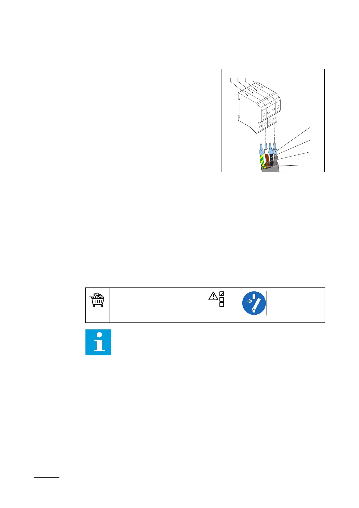
4. Connect these wires:
• PE wire (A), green/yellow, to the
terminal X10-1 (E)
• L1 wire (B), brown, to the terminal X10-2 (F)
• L2 wire (C), black, to the terminal X10-3 (G)
• L3 wire (D), grey, to the terminal X10-4 (H)
5. Tighten the screws to the correct torque. For the specification, refer to section
12.14.
7.6 Connect the interlock and DC guard cables
7.6.1 Connect the interlock and DC guard cables to the primary power
cabinet
Preliminary requirements
• Two interlock and DC guard
cables. Refer to section
12.19.5
• Wire loop
•
Note: The illustration shows the terminal block X8 of the primary power
cabinet and the connections treated in this section. For a detailed
overview of all electrical connections, refer to section 12.20.
Electrical installation of the power cabinet
9AKK107992A6488-EN | 004 47