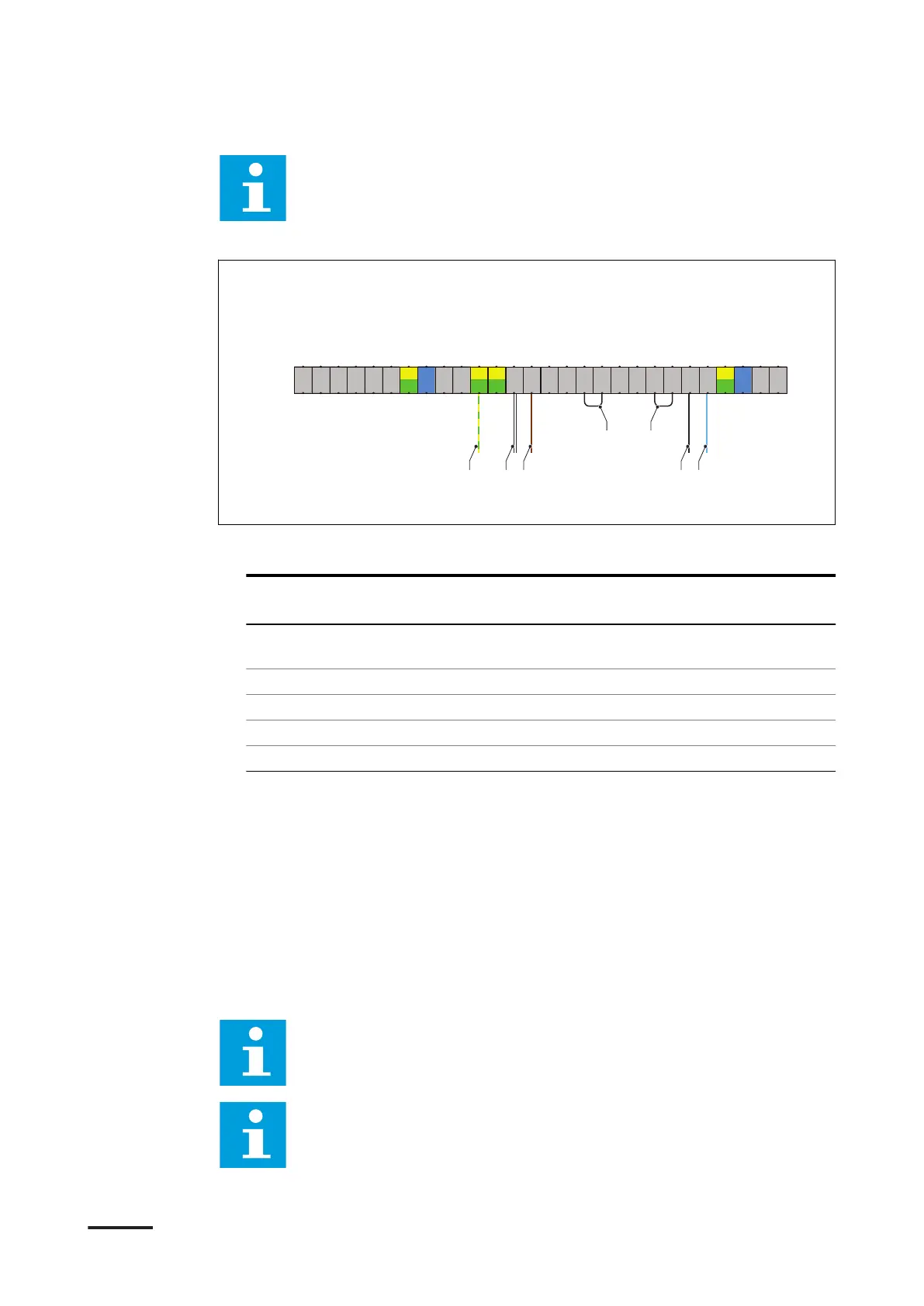
Note: The illustration shows the terminal block X8 of the secondary
power cabinet and the connections treated in this section. For a detailed
overview of all electrical connections, refer to section 12.20.
Procedure
1. Prepare ferrules for the wires that are mentioned below. Refer to section 11.2.
2. Connect these wires from the primary power cabinet:
Wire from primare pow-
er cabinet
Connect to terminal Terminal name
(A) Ground wire or shield
mesh
Earthing terminal PE
(B) IL IN 3 X8-15 IL OUT 1
(C) IL OUT 3 X8-14 IL IN 1
(D) DC guard B GND X8-5 DC guard B GND
(E) DC guard B X8-4 DC guard B
3. Connect the wire loops: .
• (F) between the terminals X8-10 and X8-11
• (G) between the terminals X8-6 and X8-7
7.7 Connect the CAN cables
7.7.1 Connect the optical CAN cables between the charge post and the
primary power cabinet
Note:
The Rx and Tx lines must be swapped between the charge the post
and the primary power cabinet.
Note: For a detailed overview of all electrical connections, refer to
section 12.20.
18 17 16192122 2024 23 15 14 13 12
11
10
9 8 7 6 5 4
-X8
123
CanH_IN
GND_CAN_IN
CanL_IN
DC-Guard B
DC-Guard B GND
IL_IN_3
IL_OUT_3
DC-Guard A 2
DC-Guard A 2 GND
IL_IN_2
IL_OUT_2
DC-Guard A 1
DC-Guard A 1 GND
IL_IN_1
IL_OUT_1
CanH_OUT
CanL_OUT
GND_CAN_OUT
Internal USE
Internal USE
Internal USE
Internal USE
Internal USE
Internal USE
PE
PE
PE
PE
A B C D E
F G
Electrical installation of the power cabinet
9AKK107992A6488-EN | 004 49