Overview 21
Layout of the NETA-21 and the NEXA-21
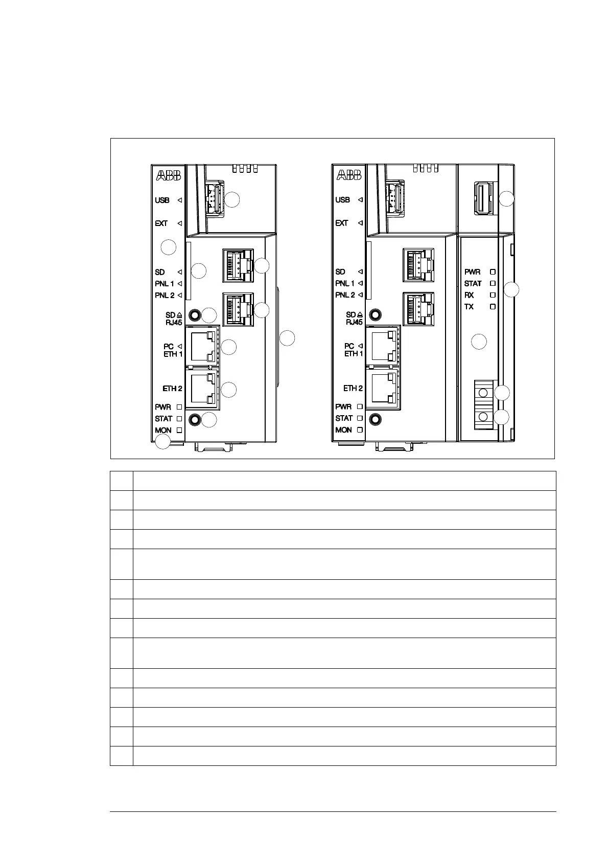
The following figures describe the front and bottom layout of the NETA-21 and the NEXA-
21.
1 Front panel labeled with a black sticker and equipped with indicator LEDs
2 PWR, STAT, MON – power, status and monitoring indicators, see LED indications
3 SD – SD/SDHC memory card slot
4 USB – USB host connector for third party extensions
5 PNL 1/PNL 2 – connector providing an interface for a panel bus that can be used for communication
with certain drive types
6a PC ETH 1 – connector providing an Ethernet connection for a locally connected PC
6b ETH 2 – connector providing an Ethernet connection for an external Ethernet network
7 Connector for the NEXA-21 unit
8 SD RJ45 – SD button is used for removing the SD/SDHC card safely and activating a DHCP server
for the first access to the user interface
9 Reset button is used for rebooting the NETA-21
10 NEXA-21 provides a fiber optics connection, secondary power input and one extra USB connector
11 PWR, STAT, RX, TX – power, status and RX/TX indicators, see LED indications
12 Fiber optic transmitter
13 Fiber optic receiver
NETA-21 NETA-21 and NEXA-21
4
4
1
5
5
3
8
11
7
10
6a
6b
9
12
13
2