30 Electrical installation
Connection via the EIA-485 port with a Modbus/RTU adapter
module
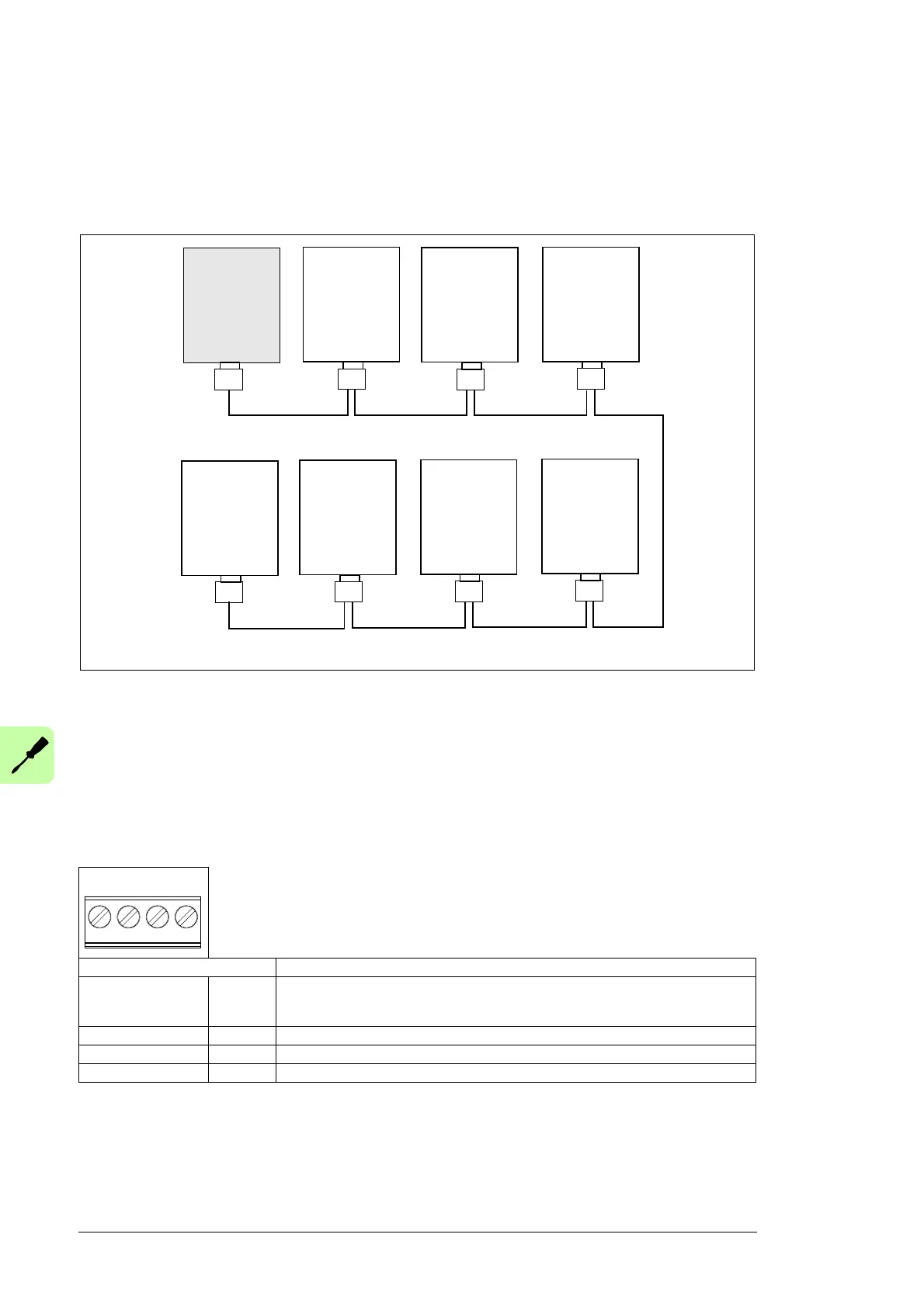
A maximum of 32 monitored Modbus/RTU devices can be connected to the same EIA-485
network. The following figure is an example of an allowable topology:
The X3 EIA-485 connector for a Modbus network is located at the bottom of the NETA-21.
See the bottom layout in section Layout of the NETA-21 and the NEXA-21. The EIA-485
(RS-485) cabling requires a shielded dual twisted pair cable. The nominal impedance of
the cable must between 100…150 ohm.
Connecting the NETA-21 to the RS-485 network
Connect the bus cable to connector X3 on the NETA-21.
The pin allocation of the X3 connector is shown below.
Signals DATA_A, DATA_B and GND_B must always be connected to all communication
modules and to the NETA-21.
X1 Description
1 SHLD Bus cable shield. Connected internally to a ground clip via an RC filter. Depending on
the installation environment, the shielding is connected to this pin on the NETA-21 or
on another location on the EIA-485 network.
2 DATA_B Data positive
3 DATA_A Data negative
4 GND_B Isolated signal ground
NETA-21
ABB drive with
an FSCA-01
or with an
embedded
EIA-485 port
Other slave
device
T = Termination
T
ABB drive with
an FSCA-01
or with an
embedded
EIA-485 port
ABB drive with
an FSCA-01
or with an
embedded
EIA-485 port
Other slave
device
Other slave
device
T
ABB drive with
an FSCA-01
or with an
embedded
EIA-485 port