and interprets that the motor is de-energized and disables the function to prevent
unnecessary trip events.
4.1.8.6 Signals
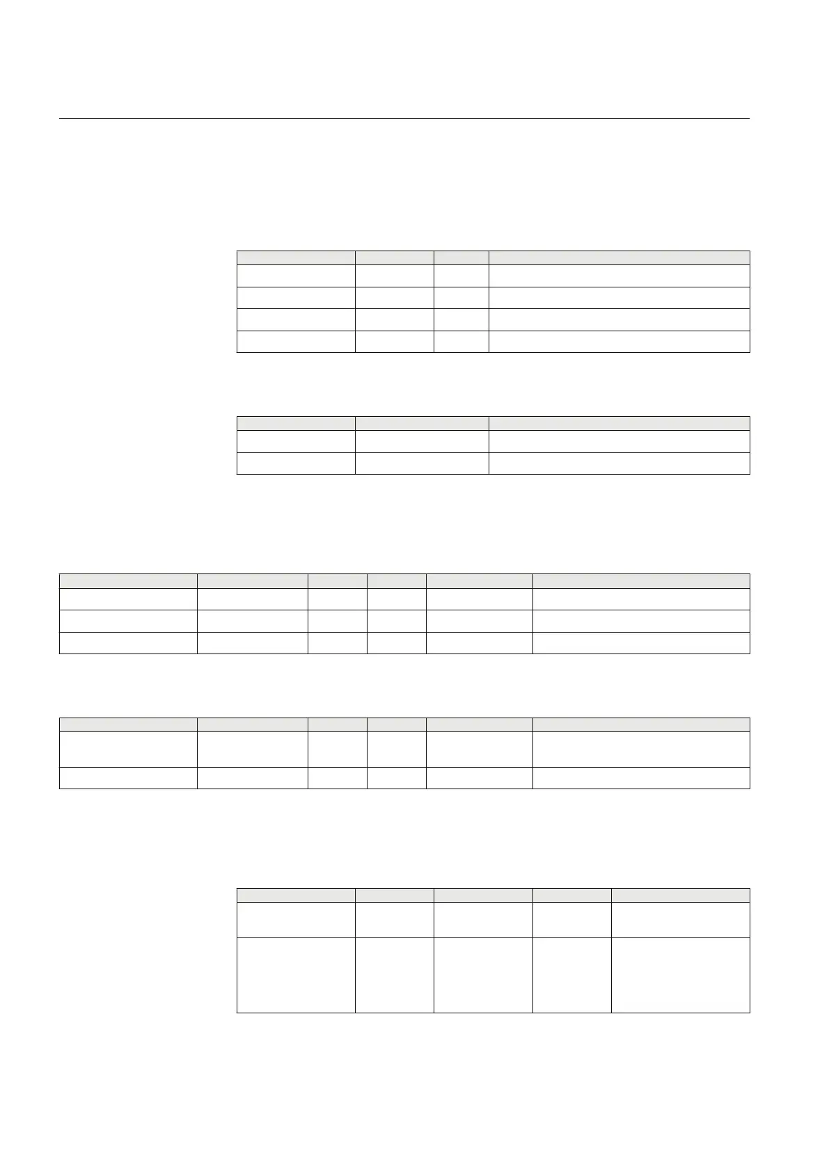
Table 250: LOFLPTUC Input signals
Name Type Default Description
I_A SIGNAL 0 Phase A current
I_B SIGNAL 0 Phase B current
I_C SIGNAL 0 Phase C current
BLOCK BOOLEAN 0=False Block all binary outputs by resetting timers
Table 251: LOFLPTUC Output signals
Name Type Description
OPERATE BOOLEAN Operate
START BOOLEAN Start
4.1.8.7 Settings
Table 252: LOFLPTUC Group settings
Parameter
Values (Range) Unit Step Default Description
Start value low 0.01...0.50 xIn 0.01 0.10 Current setting/Start value low
Start value high 0.01...1.00 xIn 0.01 0.50 Current setting/Start value high
Operate delay time 400...600000 ms 10 2000 Operate delay time
Table 253: LOFLPTUC Non group settings
Parameter
Values (Range) Unit Step Default Description
Operation 1=on
5=off
1=on Operation Off / On
Reset delay time 0...60000 ms 1 20 Reset delay time
4.1.8.8 Monitored data
Table 254: LOFLPTUC Monitored data
Name
Type Values (Range) Unit Description
START_DUR FLOAT32 0.00...100.00 % Ratio of start time /
operate time
LOFLPTUC Enum 1=on
2=blocked
3=test
4=test/blocked
5=off
Status
Section 4 1YHT530004D05 D
Protection functions
246 615 series
Technical Manual