GUID-CC4ADDEA-EE11-4011-B184-F873473EBA9F V1 EN
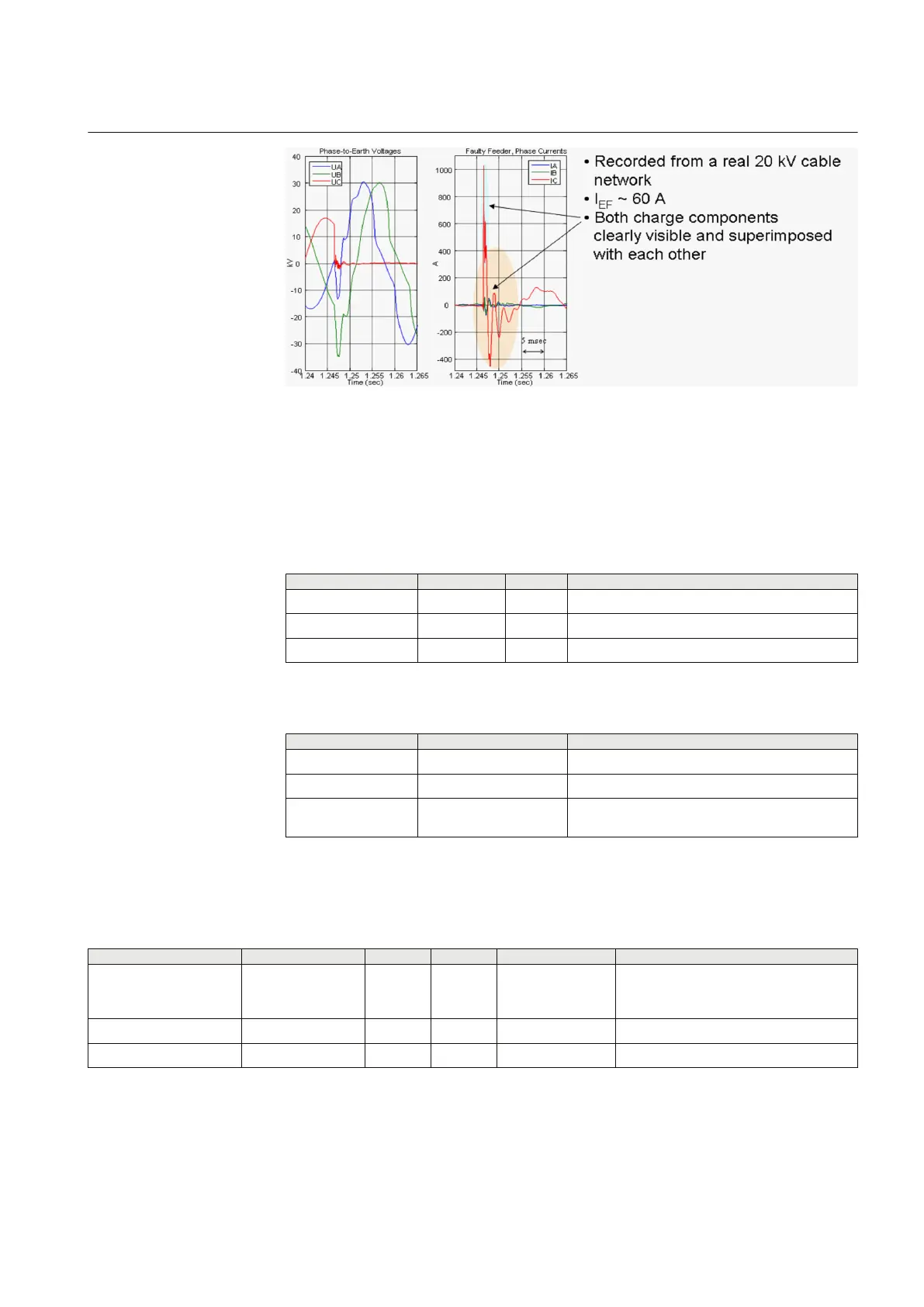
Figure 154: Example of earth-fault transients, including discharge and charge
transient components, when a permanent fault occurs in a 20 kV
network in phase C
4.2.3.6 Signals
Table 309: INTRPTEF Input signals
Name
Type Default Description
Io SIGNAL 0 Residual current
Uo SIGNAL 0 Residual voltage
BLOCK BOOLEAN 0=False Block signal for activating the blocking mode
Table 310: INTRPTEF Output signals
Name
Type Description
OPERATE BOOLEAN Operate
START BOOLEAN Start
BLK_EF BOOLEAN Block signal for EF to indicate opposite direction
peaks
4.2.3.7 Settings
Table 311: INTRPTEF Group settings
Parameter
Values (Range) Unit Step Default Description
Directional mode 1=Non-directional
2=Forward
3=Reverse
2=Forward Directional mode
Operate delay time 40...1200000 ms 10 500 Operate delay time
Voltage start value 0.10...0.50 xUn 0.01 0.20 Voltage start value for transient EF
1YHT530004D05 D Section 4
Protection functions
615 series 309
Technical Manual