By comparing the reactive components of the currents measured by the different
regulators it is possible to find out if the circulating current has been minimized.
The circulating current is minimized when the reactive components are equal.
The negative reactance method gives satisfactory results only if the phase angle of
the load current is known relatively accurately. If the actual phase angle deviates
from the phase angle setting, a regulating error occurs. However, for the cases
where there is an occasional stepwise change in the phase angle of the load, the
regulating error can be suppressed with the logic. This kind of stepwise change can
occur, for example, when a capacitor bank is switched on to compensate a reactive
power flow.
Another possibility is to use an automatic setting group change between setting
groups in different loading situations. The setting groups then have different set
values for the load phase angle.
9.5.10.3 Minimizing Circulating Current principle MCC
The MCC principle is an optimal solution for controlling the parallel transformers
of different ratings or step voltages in substations with varying reactive loads.
Since this control scheme allows the exchange of data between regulators, the
circulating current can be calculated more accurately than with other schemes.
However, a maximum of four regulators can be connected in parallel. To start the
parallel operation, the acting operation mode parameter has to be set to "MCC" for
all the regulators of the connection. Furthermore, the signal CON_STATUS must
indicate that the transformers are connected to the network. A unit that is
minimizing the circulating current must have the acting operation mode set to
"MCC". However, units that have the acting operation mode set to "Manual" do not
perform any circulating current minimization operations themselves.
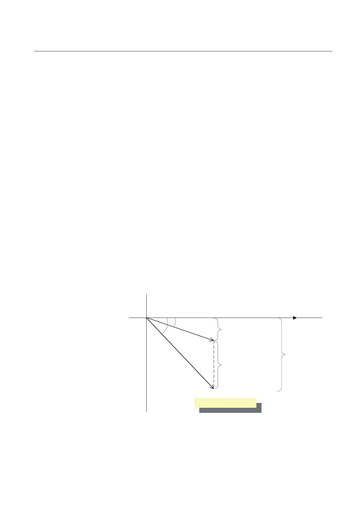
2 x Ici
I
TR1
x sin(φ
1
)
I
TR2
x sin(φ
2
)
φ
1
φ
2
U_A
Ici = circulating current
I
TR1
I
TR2
GUID-F73692B0-629D-4C0A-BFAB-648B0A832E42 V2 EN
Figure 400: The circulating current between two parallel transformers
1YHT530004D05 D Section 9
Control functions
615 series 741
Technical Manual