open circuit in any phase, a negative-sequence current flows and it is equal and
opposite to the previous load current in a healthy phase. The combination of
positive and negative-sequence currents produces phase currents approximately 1.7
times the previous load in each healthy phase and zero current in the open phase.
The negative-sequence currents flow through the stator windings inducing negative-
sequence voltage in the rotor windings. This can result in a high rotor current that
damages the rotor winding. The frequency of the induced current is approximately
twice the supply frequency. Due to skin effect, the induced current with a
frequency double the supply frequency encounters high rotor resistance which
leads to excessive heating even with phase currents with value less than the rated
current of the motor.
The negative-sequence impedance of induction or a synchronous motor is
approximately equal to the locked rotor impedance, which is approximately one-
sixth of the normal motor impedance, considering that the motor has a locked-rotor
current of six times the rated current. Therefore, even a three percent voltage
unbalance can lead to 18 percent stator negative sequence current in windings. The
severity of this is indicated by a 30-40 percent increase in the motor temperature
due to the extra current.
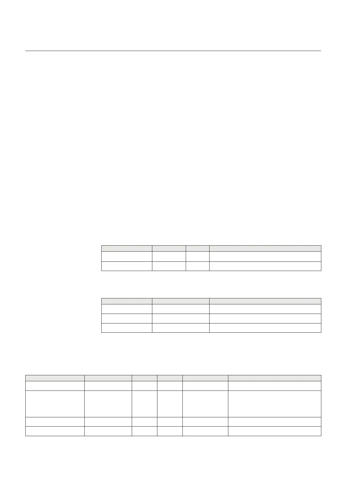
4.4.4.7 Signals
Table 377: MNSPTOC Input signals
Name
Type Default Description
I
2
SIGNAL 0 Negative sequence current
BLOCK BOOLEAN 0=False Block signal for activating the blocking mode
Table 378: MNSPTOC Output signals
Name
Type Description
OPERATE BOOLEAN Operate
START BOOLEAN Start
BLK_RESTART BOOLEAN Overheated machine reconnection blocking
4.4.4.8 Settings
Table 379: MNSPTOC Group settings
Parameter
Values (Range) Unit Step Default Description
Start value 0.01...0.50 xIn 0.01 0.20 Start value
Operating curve type 5=ANSI Def. Time
15=IEC Def. Time
17=Inv. Curve A
18=Inv. Curve B
15=IEC Def. Time Selection of time delay curve type
Machine time Mult 5.0...100.0 0.1 5.0 Machine related time constant
Operate delay time 100...120000 ms 10 1000 Operate delay time
Section 4 1YHT530004D05 D
Protection functions
464 615 series
Technical Manual