TCO
RSV
TAPCHG_FLLW
TAP_POS
I_C
U_AB
I_B
I_A
TR1_TAP_POS
TR2_TAP_POS
TR3_TAP_POS
LTC_BLOCK
RAISE_LOCAL
LOWER_LOCAL
CON_STATUS
PARALLEL
AUTO
TR2_I_ANGL
TR3_I_AMPL
TR3_I_ANGL
TR1_I_AMPL
TR1_I_ANGL
TR2_I_AMPL
Blocking
scheme
ALARM
Auto
parallel
(NRP)
t
Timer
t
TR0_I_AMPL
TR0_I_ANGL
Alarm
indication
Auto
parallel
(Follower)
Auto
parallel
(Master)
Auto
parallel
(MCC)
Auto
single
Automatic
voltage
regulation
Manual
voltage
regulation
FLLW1_CTL
FLLW2_CTL
FLLW3_CTL
PAR_FAIL
Pulse
control
RAISE_OWN
LOWER_OWN
Operation
mode
selection
PARALLEL
AUTO
BLKD_I_LOD
BLKD_U_UN
BLKD_U_OV
BLKD_I_CIR
BLKD_LTCBLK
TIMER_ON
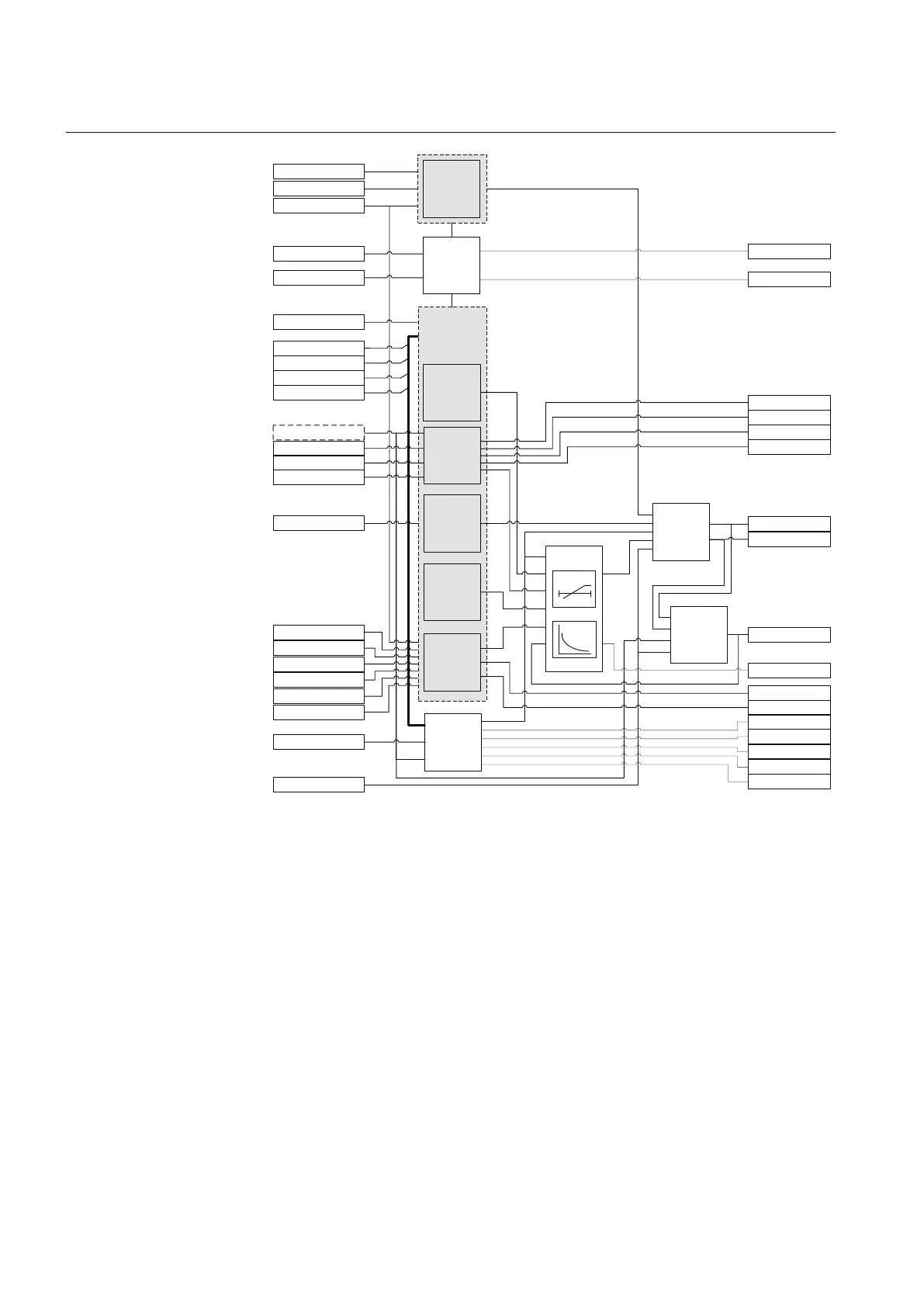
GUID-BC07A9CF-D378-4A60-AFAF-DB6021BD082D V2 EN
Figure 396: Functional module diagram
9.5.5 Voltage and current measurements
The measured voltage must be a phase-to-phase voltage from the regulated side.
Typically, it is the phase-to-phase voltage U_AB from the secondary side of the
power transformer. If the phase voltages are measured, the voltage U_AB is
calculated internally in the IED.
Currents from the secondary side of the power transformer (I_A – I_C) have
several uses.
Section 9 1YHT530004D05 D
Control functions
728 615 series
Technical Manual