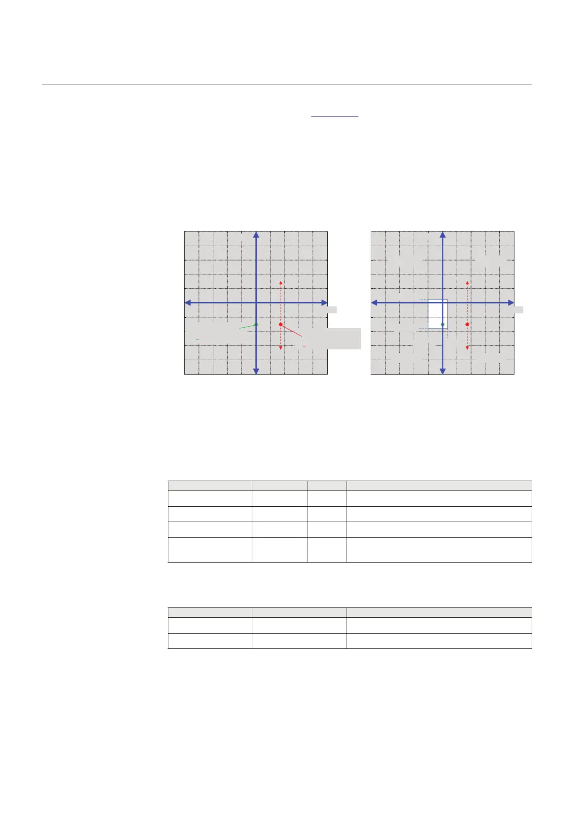
The admittance characteristic is set to cover the total admittance of the protected
feeder with a proper margin, see Figure 172.
Conductance forward = 1.73 mS · 0.2 ≈ 0.35 mS
Conductance reverse = -1.0 mS (valid range apprx. 0.5 · 1.15 - 1.2 · 1.73 = -0.6...-2.1)
Susceptance forward = 0.1 mS
Susceptance reverse = -1.15 mS · 1.2 ≈ -1.4 mS
-5
-4
-3 -2 -1 0 1 2
3
4 5
-5
-4
-3
-2
-1
0
1
2
3
4
5
Go (mS)
Bo (mS)
Backward fault:
Y
o ≈ -j*1.15mS
Forward fault,
Y
o ≈ 1.73+j*Bo mS
-5
-4
-3 -2
-1
0 1
2 3
4
5
-5
-4
-3
-2
-1
0
1
2
3
4
5
Go (mS)
Bo (mS)
0.35 mS
-1.0 mS
-1.4 mS
0.1 mS
OPERATE OPERATE
OPERATE
OPERATE
GUID-AE9BB46E-B927-43F6-881A-A96D3410268D V1 EN
Figure 172: Admittances of the example
4.2.4.7 Signals
Table 317: EFPADM Input signals
Name
Type Default Description
Io SIGNAL 0 Residual current
Uo SIGNAL 0 Residual voltage
BLOCK BOOLEAN 0=False Block signal for activating the blocking mode
RELEASE BOOLEAN 0=False External trigger to release neutral admittance
protection
Table 318: EFPADM Output signals
Name
Type Description
OPERATE BOOLEAN Operate
START BOOLEAN Start
Section 4 1YHT530004D05 D
Protection functions
334 615 series
Technical Manual