I
LOAD
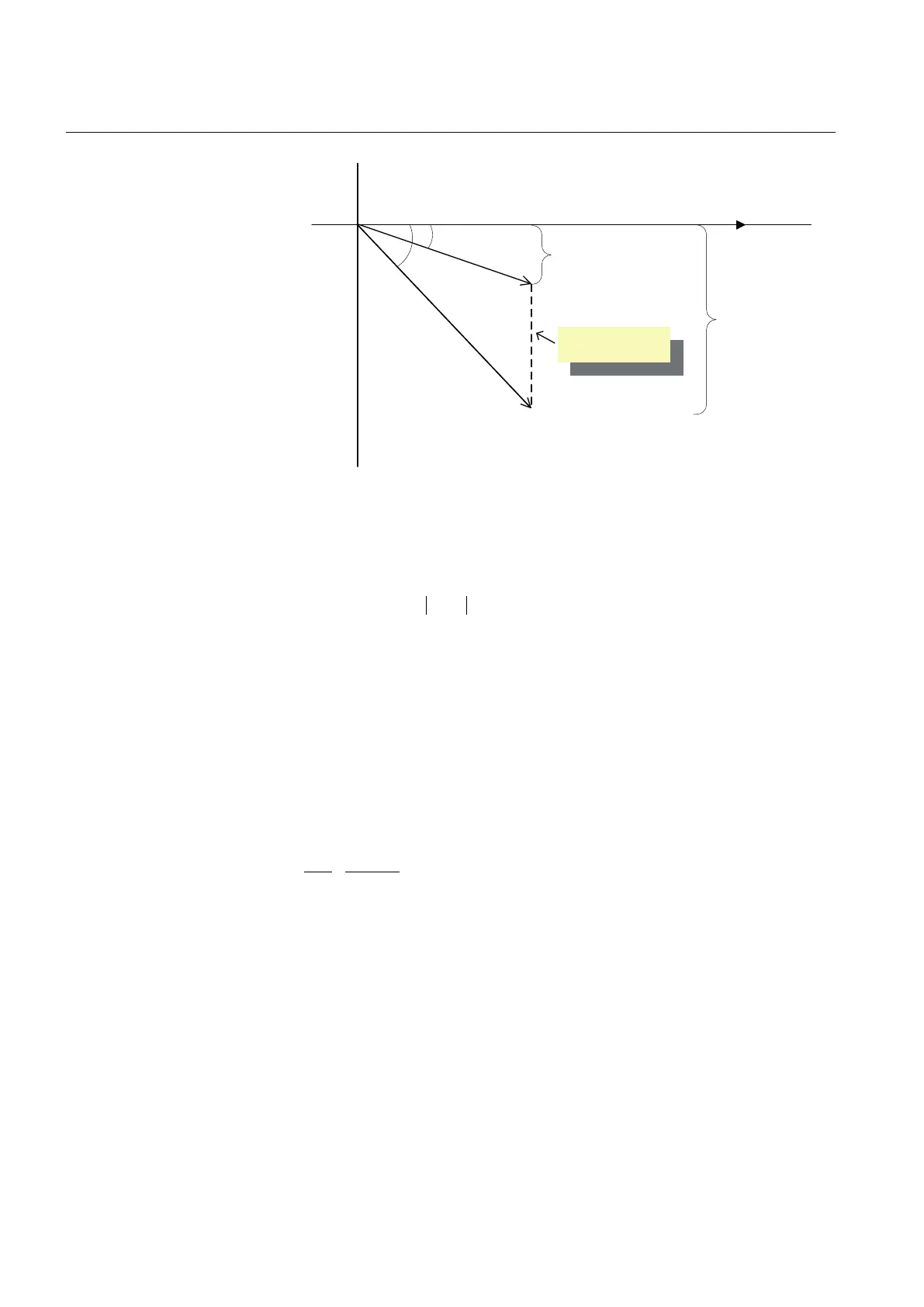
x sin(φ
LOAD
)
I
TR1
x sin(φ
1
)
φ
LOAD
φ
1
U_A
Ici = circulating
current
I
LOAD
I
TR1
I
LOAD
= I
TR1
x │cos(φ
1
)│/cos(φ
LOAD
)
GUID-2B71B160-FB76-4BE0-952F-75F42220401F V2 EN
Figure 399: The expected phase angle of the load supplied by the transformers
operating in parallel is entered as a setting value φ
Load
The regulators calculate the circulating current with the equation
I I
ci Load TR
= − × ×(sin tan cos )
ϕ ϕ ϕ
1 1 1
GUID-823FAEEA-589B-4C8E-81CD-E5FECF28BF06 V1 EN (Equation 92)
I
TR1
Average of the currents I_A, I_B and I_C
φ
1
Phase angle between U_A and I_A
φ
Load
The set Load phase angle of the load current
In the negative reactance method, the circulating current is minimized by changing
the control voltage according to the measured circulating current. The regulator
calculates the circulating current compensation term U
ci
using the equation
U
I
I
Stability
U
ci
ci
n
n
=
−
× ×
100
GUID-2A7864D3-D59F-47F9-84FD-B3F2C15178EB V1 EN (Equation 93)
I
ci
Circulating current
Stability
Stability setting (the recommended value depends on the loop impedance)
If the transformers operating in parallel have different rated currents, the value of
the Stability factor setting of the regulator should be proportional to the rated
currents, that is, the higher the rated current, the higher the Stability factor setting
value.
Section 9 1YHT530004D05 D
Control functions
740 615 series
Technical Manual