Band
width
voltage
U
ΔU
step
t
bandwidth limit
hysteresis limit
U
m
, measured voltage
U
p
, control voltage
T1 start
T1 reset
T1 start
Lower
T1
GUID-65BA0EC4-8E96-41E1-B273-3519DF5C25E1 V2 EN
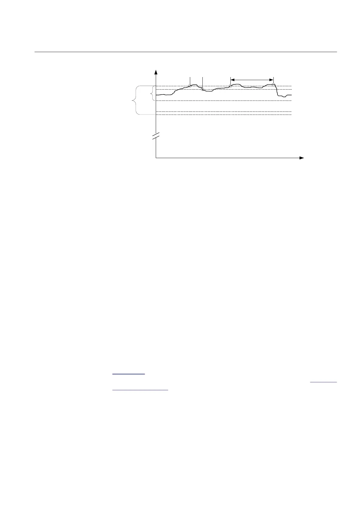
Figure 397: Voltage-regulating function. A control pulse to lower the voltage is
issued after the elapsed T1.
If the measured voltage is outside the hysteresis when the delay counter T1 reaches
its setting value, the raising or lowering output relay is activated. This activates
either output pulse RAISE_OWN or LOWER_OWN, and the motor drive of the tap
changer operates. The status of these outputs can be read from the output data
RAISE_OWN or LOWER_OWN.
If the measured voltage falls or rises within the hysteresis limits during the
operating time, the delay counter is reset.
The pulse length can be defined with the LTC pulse time setting. The default value
is 1.5 seconds.
A short delay same as the typical tap changer operating time is active before the
start of the next operating timer is possible. For OLATCC, the delay is set to 6
seconds. If one tap changer operation is not enough to regulate the transformer
voltage within the hysteresis limits, a second adjustable delay T2 (Control delay
time 2), usually with a shorter time setting than T1, starts. This delay is used for the
control commands within the same sequence until the recovery of voltage occurs.
The delays T1 and T2 can be selected either with definite or inverse time
characteristics. In the inverse time mode operation, the operating time depends on
the difference between the control voltage and the measured voltage as shown in
Equation 95. The bigger the difference in the voltage, the shorter the operating
time. More information on the inverse time operation can be found in the OLATCC
timer characteristics chapter.
Regulation equation
The simple regulating principle is often complemented by additional features to
take the voltage drop of lines into account (line drop compensation), coordinate the
regulation of parallel transformers and change the voltage level according to the
1YHT530004D05 D Section 9
Control functions
615 series 733
Technical Manual