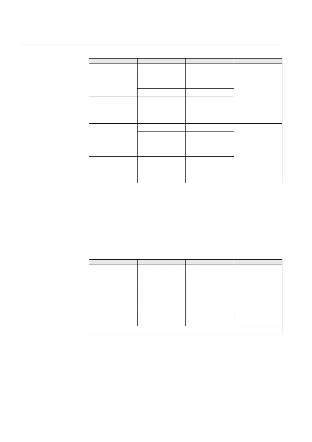
Table 670: 2-wire EIA-485 jumper connectors
Group Jumper connection Description Notes
X4 1-2 A+ bias enabled COM2
2-wire connection
2-3 A+ bias disabled
X5 1-2 B- bias enabled
2-3 B- bias disabled
X6 1-2 Bus termination
enabled
2-3 Bus termination
disabled
X7 1-2 B- bias enabled COM1
2-wire connection
2-3 B- bias disabled
X8 1-2 A+ bias enabled
2-3 A+ bias disabled
X9 1-2 Bus termination
enabled
2-3 Bus termination
disabled
The bus is to be biased at one end to ensure fail-safe operation, which can be done
using the pull-up and pull-down resistors on the communication module. In 4-wire
connection the pull-up and pull-down resistors are selected by setting jumpers X4,
X5, X7 and X8 to enabled position. The bus termination is selected by setting
jumpers X6 and X9 to enabled position.
The jumpers have been set to no termination and no biasing as default.
Table 671: 4-wire EIA-485 jumper connectors for COM2
Group
Jumper connection Description Notes
X4
1-2 A+ bias enabled
COM2
4-wire TX channel
2-3
A+ bias disabled
1)
X5
1-2 B- bias enabled
2-3
B- bias disabled
1)
X6
1-2 Bus termination
enabled
2-3 Bus termination
disabled
1)
Table continues on next page
Section 13 1YHT530004D05 D
IED physical connections
856 615 series
Technical Manual